Author Topic: Shay Locomotive  (Read 22861 times)

Offline Dan Rowe

  • Jr. Member
  • **
  • Posts: 26
  • Country: us
  • Dripping Springs TX
Shay Locomotive
« on: July 22, 2012, 02:17:07 PM »
I have spent a few years researching the drawing records of the Lima Locomotive Works and I have drawn 5 Shay locomotives and a really nifty geared 4 wheel critter with side rods all from original Lima records. The bulk of this work appeared in "Steam in the Garden" a small mom and pop magazine that was edited by the late Ron Brown a steamup buddy of mine and a real friend to the G1 live steam community,

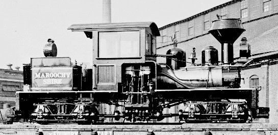
The series of articles I wrote was titled The Nuts and Bolts of Shays and they are about the engineering of Shay locomotives. The series concluded with several articles that included all the drawings I could locate for Shop number 2800. This was a small 2' gauge 10 ton Shay with 2-6"x10" cylinders that ran at the Mapleton Tramway in Queensland Australia.

Issue #100 was the start of the Mapleton section Ron gave me a double fold out so the full up drawing was printed in the build scale of 7/8" to the foot. Both sides and the front and back of the locomotive are drawn full model size.

Here is the photo of Shop number 2800 posted with permission of the Allen County Historical Society Lima Ohio.


The frame seamed like the logical place to start so I had to think about milling scale I beam to get a good looking model. I have tried several ways that did not give satisfactory results so this time I used a 100 tapered ball end mill after the 1/2" square 12L14 stock was roughed to size. Here is the set up for the mill.


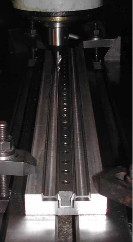
I found out right off that I had to make the same cut on both sides of the frame stock to prevent warping. Here is the photo of the first attempt that proved that concept.


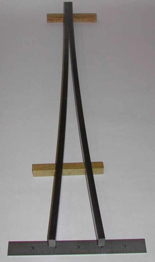
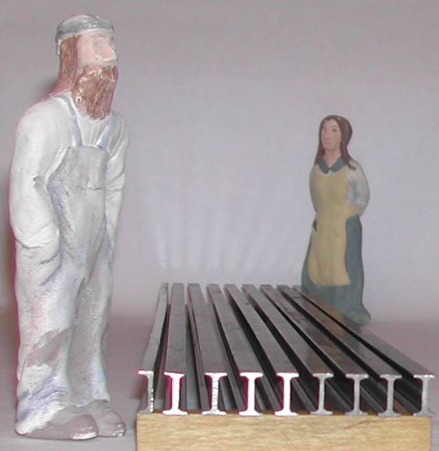
Here is the finished I beams and some channel stock for final inspection.


Next up is a bit of rivet practice, the tools are modified versions of what is in the Harris boiler book fitted to a heavy duty Starrett automatic center punch.


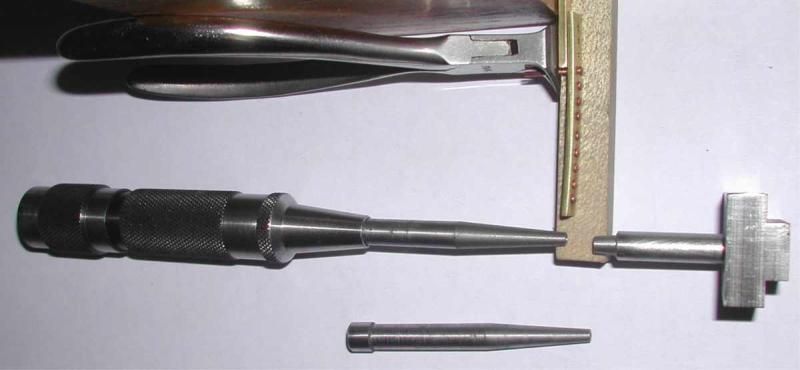
The small section of brass stock is a guide that is 1.5 times thicker than the body of the rivet so i can use the flush cutter to leave the proper amount to from a rivet head the bucker for the vise is also shown.

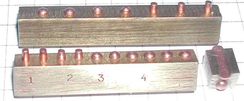
Here is an early practice run the numbers more or less match what is in the boiler book but I reduced the operation to two dies for the center punch.


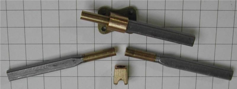
Here is a couple of  master patterns. The truss pads are right and left handed so I made a single master that the angle can be adjusted for either way. The left and right core are also shown. The little truss post guide was tricky to machine, I am really glad that I only have to make one of those. The grid is 1/4" square.


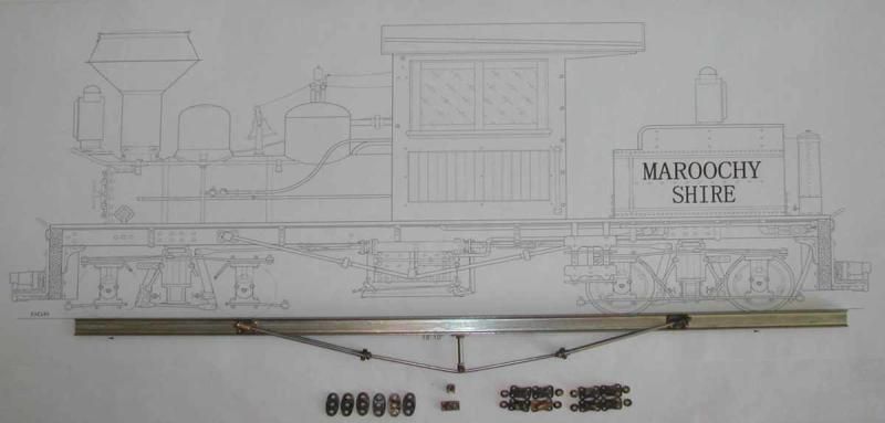
Here are the parts for a test fit. The frame is 19.25" long.


More to come to catch up to date.

Dan
« Last Edit: July 22, 2012, 05:27:06 PM by Dan Rowe »
Shayloco Dan

Offline saw

  • Hero Member
  • *****
  • Posts: 1003
  • Country: se
  • lucky amateur
    • Svenssons AckordsWerkstad
Re: Shay Locomotive
« Reply #1 on: July 22, 2012, 02:49:22 PM »
Wow this looks good. I will folow this log with the greatest intresst.  :clap: :clap: :clap:
_________________________
Greetings / Benni
http://myprojecty.wordpress.com/category/steam-engine/

Rob.Wilson

  • Guest
Re: Shay Locomotive
« Reply #2 on: July 22, 2012, 05:18:43 PM »
Hi Dan

The Shay is defiantly an interesting  Loco , there was one running today at our club .


Rob

Offline krv3000

  • Hero Member
  • *****
  • Posts: 2183
  • Country: gb
Re: Shay Locomotive
« Reply #3 on: July 22, 2012, 05:21:33 PM »
sos a bit of topic wot club rob

Rob.Wilson

  • Guest
Re: Shay Locomotive
« Reply #4 on: July 22, 2012, 05:24:40 PM »
Hi Bob

Tyneside Society of Model & Experimental Engineers  :thumbup:


Rob

Offline doubleboost

  • Madmodder Committee
  • Hero Member
  • *****
  • Posts: 1619
  • Country: gb
  • Newcastle Upon Tyne
Re: Shay Locomotive
« Reply #5 on: July 22, 2012, 05:25:31 PM »
Hi Dan
This is going to be some build :drool: :drool: :drool:


Rob
More pictures please  :drool: :drool: :drool:


John (DAFT TWAT) :D
« Last Edit: July 22, 2012, 05:30:07 PM by RobWilson »

Offline krv3000

  • Hero Member
  • *****
  • Posts: 2183
  • Country: gb
Re: Shay Locomotive
« Reply #6 on: July 22, 2012, 05:26:21 PM »
hi yep looking fowerd to the bild

Offline Dan Rowe

  • Jr. Member
  • **
  • Posts: 26
  • Country: us
  • Dripping Springs TX
Re: Shay Locomotive
« Reply #7 on: July 22, 2012, 05:59:09 PM »
Thanks for the coments, Rob that looks like Kozo's first Shay which is where I started dreaming this project up.

The Lima drawings that survived include some of the tools so I had to make some of the jacks that would have been included in the tool box for this Shay.

Here is the drawing of the smallest of the Lima jacks I have even seen a photo of one of these in use.


I used a 10-32 hex head socket screw to make a set of 4 jacks in 7/8" scale. The big one is one of the projects I made in shop class in college.


The channel section was cut and drilled for the angle brackets. The ends are filed to fit the I beam profile.


I am making both the Shays that went to the Mapleton Tramway. They were mainly the same built to the same plan but with some slight changes to the frame and a few other accessories like the boiler. The frame center plates proved very difficult to cast and as they are a fairly simple part that is easy to machine from solid I made the second set from solid.

I had a handy chunk of brass hex so the first step was to use the lathe for a center hole then over to the mill and the 5C indexer is used to rough out the shape.


Back to the lathe for the round sections and parting off.


Now to drill the cross holes.


Here is more scale stock made from hot rolled stock. I carefully kept the mill scale finish where it will show.


Here is a clamp and jig to drill the corner brackets.


Now both sets of cross members assembled.


Dan
Shayloco Dan

Offline tomfilery

  • Jr. Member
  • **
  • Posts: 7
  • Country: gb
Re: Shay Locomotive
« Reply #8 on: July 27, 2012, 04:00:41 PM »
Dan,

I admired your beautiful work on HMEM previously.

In this thread I'm intrigued by your "rivet practice" post.  Are you able to tell us a little more about the tools you are using to form those very nice heads (and in only two operations, if I read correctly)?

Kindest Regards Tom

Offline Dan Rowe

  • Jr. Member
  • **
  • Posts: 26
  • Country: us
  • Dripping Springs TX
Re: Shay Locomotive
« Reply #9 on: July 27, 2012, 08:47:42 PM »
Tom, thanks for the interest.
I read up on rivets and the closest model solution I could come up with was to find a ball end mill twice the body size. This should really be 1.75 times the body but I did not want to make my own cutters.


The first die I used a center cutting end mill the size of of the rivet body. The depth of the cut was the body diameter. I then used a small counter bore or a spot drill to machine the cone on the end of the die.

The bucker and the final die are made with the ball mill to match the factory head as close as possible.

I used tool steel and did not bother to harden it and looking at the photo of the one I did today, I think I should recut the dies and harden them.

Dan
Shayloco Dan

Offline steamer

  • Jr. Member
  • **
  • Posts: 86
  • Country: us
Re: Shay Locomotive
« Reply #10 on: July 27, 2012, 09:06:43 PM »
That is sweeeet Dan!

Nice build!

Dave
"Mister M'Andrew, don't you think steam spoils romance at sea?"
Damned ijjit!

Offline tomfilery

  • Jr. Member
  • **
  • Posts: 7
  • Country: gb
Re: Shay Locomotive
« Reply #11 on: July 28, 2012, 05:08:06 AM »
Dan,

Many thanks for your response - I might well have to try to make something similar - and note your comments and observations about hardening being necessary.  One small question - the "bucker" (which you indicate you mount in the vice) - is that the dolly to hold the rivet head steady, whilst you form the head on the other end?

Your corner bracket jig is also really neat - I'd been toying with various ideas how to do the same job for producing multiple brackets for a railway wagon project in 16mm/ft scale.  Your solution gives me a range of other options to explore.

Please keep up the good work.  I'm glad you are getting back to this project and am looking forward to further instalments.

Regards Tom

Offline Dan Rowe

  • Jr. Member
  • **
  • Posts: 26
  • Country: us
  • Dripping Springs TX
Re: Shay Locomotive
« Reply #12 on: July 28, 2012, 06:49:45 PM »
Tom, yes dolly is another name for bucker which is the term used on this side of the pond for the guy bucking the rivet or the tool in his hand.

Now time to drill the I beams for the frame spreader assembly.

Here is the first side with the drill jig clamped. The distance is set by the scale. The brass bar clamp is a third hand to make it easy to set the C clamp.


Now the set up for clamping the other side with the same setting on the square.


I knocked off for the day and drilled the holes the first thing the next day only to find out that now the assembly did not match the drawing. This was not the first goof and most likely not the last one so I needed a new way to plug the bad holes.

I was using my Knipex pliers to smash tiny sections of rivets in the bad holes but I had to use blocks of steel to get past the beam flanges. This was a balancing act and a lot of the tiny rivet pieces fell out never to be seen again.
 
My solution was to add tool steel mashing blocks to the pliers which are simple to operate with one hand.


This photo shows mashed rivet on the top and the same section repaired on the lower beam.


Now the frame is taking shape.


Dan
« Last Edit: July 28, 2012, 07:58:10 PM by Dan Rowe »
Shayloco Dan

Offline Dean W

  • Hero Member
  • *****
  • Posts: 571
  • My kingdom for a lathe!
    • Projects web pages
Re: Shay Locomotive
« Reply #13 on: July 28, 2012, 10:02:51 PM »
This is some mighty fine work here, Dan.  Your attention to detail is admirable.
Your work on the channel iron came out really nice!
Dean W.

Shop Projects:
http://www.deansphotographica.com/machining/projects/projects.html

Praise the Lord and pass the Carbide!

Offline Dan Rowe

  • Jr. Member
  • **
  • Posts: 26
  • Country: us
  • Dripping Springs TX
Re: Shay Locomotive
« Reply #14 on: July 29, 2012, 12:47:53 PM »
Dean thanks for the complement. I like lots of detail and some of it does not even show like the fact that the truss pads have a small spherical washer under the nut just like the drawing.

I have a lost wax casting setup to make the parts I need for this project here is the casting bench.


The blue box is the kiln and the orange box is the programmable controller. In the back the black box is the vacuum pump. The short blue box in the foreground is the vacuum table setup with a gasket for casting.

I mostly do small pours so I use a hand held crucible that I use the rosebud tip on my OA rig for the heat source. The stainless steel tubes are flasks for the investment.

I have an electric crucible but I have not really done many pours that need that much metal. The SS things are production flasks and at some time I will upgrade my operation to use them.


Here is the rubber vulcanizer and the wax pot.


Now to show how I make use of the equipment I will show the steps to make the drawheads.

First for a complicated part I start with wax and make a model 5% larger than the scale print. The drawhead used for S/N 2800 was unusual and I think it was a special case for the Mapleton Tramway. The drawhead on the left was the one used for the Gilpin #1 Shay and it is a lot more typical for small early Shays. I noticed the similarity so I made both at the same time.


The wax is cast to make a metal pattern for a rubber mold. This is the master and the core. The other core with the square edges was used to help make the wax pattern.


Here is the whole assembly in a rubber mold frame ready for the rubber to be added.


The rubber mold is shown cut open with the cores in place. The blue wax is ready for cleanup and investment.


The finished drawhead is placed on a scale drawing for comparison.


Dan
 
Shayloco Dan

Offline Dan Rowe

  • Jr. Member
  • **
  • Posts: 26
  • Country: us
  • Dripping Springs TX
Re: Shay Locomotive
« Reply #15 on: July 30, 2012, 08:41:25 AM »
In the process of writing this up, my wife Alicia who is usually the photographer found an early set of photos with her brother John helping with the oven.

I mostly use a hand held crucible as I mentioned and that takes all my hands one for the torch and one for the crucible...okey I see that I am holding both items in one hand and looking over my shoulder but the metal is not hot yet.


Pouring the bronze after John took the flask out of the oven and placed it on the vacuum table and turned on the vacuum.


Molten bronze on vacuum table.


John inspecting the part just out of the investment.


Here is the piece just cast with a few other early Shay castings and a Stock Drive Products bevel gear.


Dan
Shayloco Dan

Offline Dan Rowe

  • Jr. Member
  • **
  • Posts: 26
  • Country: us
  • Dripping Springs TX
Re: Shay Locomotive
« Reply #16 on: August 03, 2012, 02:19:53 PM »
Back to the frame here are the drill blocks for the frame. The reason there are 2 in the photo is the top one is like the drawing. I used thicker channel then the drawing so I had to make a new block to match my stock.


I made the I beam the true overall cross section size with a thicker web. On second thought I should have matched the flange dimensions and made a wider beam. That would have given the correct flange depth to rivet to not a slightly narrower flange. I need all the room I can get to rivet to the flange.


This is the drill guide to drill the frame angles attached to the ends of the I beams.


Here is the full set of running board brackets for Shay Plan 1553. The short ones are on the left or the fireman's side and the long ones are on the engine side with the engineer.


This is the bending and drilling tool. The top screw acts as a stop and a clamp for drilling.


The setup to bend the odd short bracket.


Both styles of left side brackets with a slice of I beam stock.


Dan
Shayloco Dan

Offline saw

  • Hero Member
  • *****
  • Posts: 1003
  • Country: se
  • lucky amateur
    • Svenssons AckordsWerkstad
Re: Shay Locomotive
« Reply #17 on: August 03, 2012, 04:20:03 PM »
Very nice done, thanks for showing  :clap:
_________________________
Greetings / Benni
http://myprojecty.wordpress.com/category/steam-engine/

Offline Dan Rowe

  • Jr. Member
  • **
  • Posts: 26
  • Country: us
  • Dripping Springs TX
Re: Shay Locomotive
« Reply #18 on: August 05, 2012, 09:59:02 AM »
Benni thanks for stopping by.

The holes for riveting the running board brackets to the I beam were drilled in both parts with a single setup. Here is the drill guide.


And here is the setup in the drill vise.


I made two small blocks that just fit in the I beam flange.


I used the drill guide to spot the holes then used a ball end mill to make the pocket for the rivet head. I goofed with the first attempt so I did a second try.


This is the setup to rivet the running board bracket.


I made another jig for the grab irons. 14 gauge fence wire is nearly exactly the size required but simply smashing it would not make tabs large enough so a fabrication seamed the simple way.


Here is the silver solder operation and a finished bracket.


Here is the frame still missing the grab irons and a bunch of other parts.


I have several more frame parts in progress and I will add them when they are complete.

Dan
Shayloco Dan

Offline Dan Rowe

  • Jr. Member
  • **
  • Posts: 26
  • Country: us
  • Dripping Springs TX
Re: Shay Locomotive
« Reply #19 on: August 12, 2012, 10:41:06 AM »
I am making forward progress on this project. The end timber braces will be attached to the bottom end of the frame rails and the end timbers. The last photo in the previous post shows the location of the braces.

The end timber braces are different on the Dulong and the Mapleton. The old forged braces were replaced with a steel casting by the time the Mapleton was built. I made a pattern for a casting but I was not happy with it and rubber molds are not the best for holding close tolerances. I decided to have a go at machining the brace.

I chose some true wrought iron as it is easy to machine and I just like working old iron. The piece i used had spent over 50 years as part of a boat house on lake Michigan and I suspect that was not the first use.

Here is the stock in the chuck to bore a 1/2" hole.


I do not have a DRO on my mill so I added mill stops to the X axis to make milling a pocket simpler. I have a set of round gauge blocks tapped 1/4-28 so I tapped the ends of the stops for the same thread.


This is the setup to mill the pocket with a 1/8" ball mill. The coaxial indicator located the 1/2" hole and the other indicator is to calculate the backlash on the y axis.


This photo shows the original stock with very heavy rust. Notice the fracture section which really shows the grain structure of wrought iron.


I used sacrificial backers to mill the braces to length. The web section is 0.055" and most likely would have taken the light cuts but I hate taking chances.


The milling is complete and the parts are ready to be cut in two sections.


Here is the full set of end timber braces ready to be drilled for the frame and the timbers. They are not steel castings but I like the way they look.


Dan
« Last Edit: August 12, 2012, 11:07:36 AM by Dan Rowe »
Shayloco Dan

Offline saw

  • Hero Member
  • *****
  • Posts: 1003
  • Country: se
  • lucky amateur
    • Svenssons AckordsWerkstad
Re: Shay Locomotive
« Reply #20 on: August 12, 2012, 10:43:22 AM »
Nice work   :clap: :clap:
_________________________
Greetings / Benni
http://myprojecty.wordpress.com/category/steam-engine/

Offline narrowgauger

  • Jr. Member
  • **
  • Posts: 10
Re: Shay Locomotive
« Reply #21 on: August 12, 2012, 07:20:24 PM »
Hi Dan

great work so far.  Even nicer is to see you using a superb lathe.  I have been using a 210 and 360 for over 30 years and would not swap them for anything else.

keep the pictures coming.

have fun & stay cool
Bernard

Offline Dan Rowe

  • Jr. Member
  • **
  • Posts: 26
  • Country: us
  • Dripping Springs TX
Re: Shay Locomotive
« Reply #22 on: August 13, 2012, 03:49:01 PM »
Thanks for the interest Benni.
Yes Bernard the 360 is a nice lathe and the chucks are just the size I need for a lot of the parts I make. I have a South Bend heavy 10 but I usually only use it with 5C collets and do the chuck work with the 360. I have a 5C mount for the 360 chucks which makes going from the lathe to the mill spin indexer a simple operation.

No worries I will post photos when I have new parts.

Dan
Shayloco Dan

Offline Dan Rowe

  • Jr. Member
  • **
  • Posts: 26
  • Country: us
  • Dripping Springs TX
Re: Shay Locomotive
« Reply #23 on: August 18, 2012, 04:00:10 PM »
Benni, I used the trick I saw you use on the compound and used a center drill for a slot drill...thanks for the tip it came in handy.


I finished the frame timber braces. They needed a spot face for the bolts. The scale hole size worked out to 0.059" which works really good for a 0-80 bolt.


I made a drill guide to drill the rivet holes for the timber brace and the frame at the same time. The guide needed clearance for the radius so I used a small center drill to mill the slot and the clearance at the same time.


I worked myself into a bit of a corner as I have already added the running board brackets to the first frame. Well I forgot the hose brackets on the left side. Most Shays were equipped with a siphon that is a steam educator to pump water from a near by water source. The siphon was used on the Mapleton Tramway and several photos show the hose and one shows water being pumped from a line side tank.

It took me a while to come up with a solution and it was a tiny rivet press. The body of the press is 1/4" steel, and the screw is a 8-32. The gap in the press was cut after the hole was blind tapped for the bottom die. The upper section of the bottom die has a 5/64" hex so it can be installed with a nut driver. I tapped a small section of aluminum round to hold the screw and bottom die for machining. I used another screw to lock the bottom die in the holder. The pointed screw in the holder was used to mark the high and low point of operation of the press to check for tool clearance. The hose bracket was attached flat and rolled for the hose after it was attached.


Dan
Shayloco Dan

Offline ozzie46

  • Sr. Member
  • ****
  • Posts: 260
  • Country: us
Re: Shay Locomotive
« Reply #24 on: August 18, 2012, 07:01:13 PM »
Nice recovery! Well thought out and done.       :smart: :smart:

 Ron