Author Topic: Shay Locomotive  (Read 22852 times)

Offline Dan Rowe

  • Jr. Member
  • **
  • Posts: 26
  • Country: us
  • Dripping Springs TX
Re: Shay Locomotive
« Reply #25 on: August 26, 2012, 09:03:48 AM »
Ron thanks for the support. I got a bit of shop time for paint. The top frame is the Mapleton the bottom frame is the Dulong.

I really hate to paint but I had to get to it some time.

Dan
Shayloco Dan

Offline Dan Rowe

  • Jr. Member
  • **
  • Posts: 26
  • Country: us
  • Dripping Springs TX
Re: Shay Locomotive
« Reply #26 on: September 02, 2012, 02:25:29 PM »
I am making headway on reassembly of the frames after painting them.

The Mapleton end timbers are nearly complete. I have to cast up the push pole pockets and add them. The Mapleton end timbers are not typical Shay construction. The L angle stiffners were not normally used. The Dulong end timbers when complete will show the typical Shay construction.


My new plan for the carriage bolts is to use 1.2mm nickle silver optical screws. They come with a cheese head with no slot. I just rivet the heads and trim to length. I was using 3/64" steel rivets that I was threading 00-90... that was a lot of work for not really satisfying results.

The nickle silver 1.2mm nuts are 2.2mm AF which is a bit large for a 1.2mm bolt. I made a test mandrel to see if it was simple to cut them down to 5/64" using my 24 pin 5C indexer. This worked so I made a mandrel with matching 3/16" hex ends. The flat on the top matches the key on my 3/16" hex collet which has points up when the indexer is at zero. I drilled a hole so I could install a replaceable 1.2mm screw to mount the nut. The other bit in the photo is a hex file button to reduce the nuts with a file. That works fine but it is slow and after I dropped the third one never to be seen again   :doh: I needed a new method.


Here is a photo of my small bolt choices.
Top-- 12 BA the bolt head is 2.5mm and larger than the BA standard.
Second--00-90 brass bolt with 5/64" hex.
Third--1.2mm optical screw with 2.2mm nut.
Fourth--1.2mm optical screw with riveted head and 5/64" nut.
Fifth--1.2mm brass with 5/64" nut
Sixth--3/64" steel rivet with 00-90 thread
Bottom--1.2mm shop made bolt with 5/64" hex head and 5/64" square nut.


I am using a small press to rivet the heads of the optical screws. The scrws are 9/16" long so I drilled a 1.2mm hole in a 1/2" block of steel. To eject the finished screw I just press the die on a flat hard surface an screw pops out.


Here are some fancy jewelry items that have 1.2mm threaded holes. There is all sorts of studs available including skulls and spiders.


Dan
Shayloco Dan

Offline saw

  • Hero Member
  • *****
  • Posts: 1003
  • Country: se
  • lucky amateur
    • Svenssons AckordsWerkstad
Re: Shay Locomotive
« Reply #27 on: September 02, 2012, 02:30:22 PM »
Nice work, you have an very intressting project here  :thumbup: :thumbup:
_________________________
Greetings / Benni
http://myprojecty.wordpress.com/category/steam-engine/

Offline BK

  • In Memoriam
  • Jr. Member
  • *****
  • Posts: 74
Re: Shay Locomotive
« Reply #28 on: November 19, 2012, 05:17:58 PM »
Wow! I'll be following this one for sure, my great grandfather and his brothers ran 2 Shays and a climax at their sawmill at Canungra Queensland AU.


If it aint broke, don't fix it!

Offline Dan Rowe

  • Jr. Member
  • **
  • Posts: 26
  • Country: us
  • Dripping Springs TX
Re: Shay Locomotive
« Reply #29 on: November 20, 2012, 10:25:16 AM »
Many thanks for the photos.

Very interesting that is S/N 2478 which was built to the same plan as both Mapleton Tramway Shays. I included the steam bracket supplemental drawings for all the gauges built in the drawings that were in "Steam in the Garden". So 42" gauge should be no issue.

Dan

Edit on closer inspection the top photo is S/N 2371 as it was #3 the lower photo is of course the Climax.
« Last Edit: November 20, 2012, 11:10:41 AM by Dan Rowe »
Shayloco Dan

Offline BK

  • In Memoriam
  • Jr. Member
  • *****
  • Posts: 74
Re: Shay Locomotive
« Reply #30 on: November 21, 2012, 07:33:16 PM »
 :doh: Same bridge, wrong engine :bang: this is the one I wanted.

If it aint broke, don't fix it!

Offline Dan Rowe

  • Jr. Member
  • **
  • Posts: 26
  • Country: us
  • Dripping Springs TX
Re: Shay Locomotive
« Reply #31 on: November 22, 2012, 10:49:56 AM »
Wow now we are talking that is S/N 2478.

Mostly it is standard Shay built to Plan 1553. It has the Lima diamond stack for wood and the old style cast headlight bracket. The truck bolsters are wood like the Dulong trucks. The front end beam has been changed from wood to a steel section and the drawhead is not original.

The thing that really stands out to my eye is the steam dome. The Lima records say that the boiler is a 27-3/4" straight boiler but the steam dome looks round like a boot boiler. I checked the boiler print drawing number in my records and it is not the standard Plan 1553 boiler. Drawing card 15454 was not the usual boiler there is a note that says it was built to Australian rules.....very interesting.

Both the boilers for the Mapleton Tramway were special cases with copper fireboxes. They are very similar but not the same my guess is the Board of Trade Rules changed after the first one so a new drawing had to be made for the second boiler.

I suspect that the boiler for S/N 2478 also had a copper firebox. I guess i will have to get the drawing to find out for sure.

Dan

Edit: I said the steam dome was round and that is not the unusual part as the standard boiler has a round steam dome. It is the diameter that is much larger than I expected. The boot boilers have a round firebox that extends to the steam dome. That is what the boiler in the photo looks like but the straight boiler is a normal locomotive boiler with a rectangular fire box and a smaller steam dome.
Shayloco Dan

Offline Dan Rowe

  • Jr. Member
  • **
  • Posts: 26
  • Country: us
  • Dripping Springs TX
Re: Shay Locomotive
« Reply #32 on: January 05, 2013, 02:25:23 PM »
I have made a bit of progress on this project. I have nearly all of the frame castings done so that section is nearly complete.

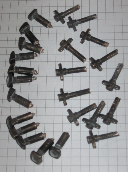
I made the push pole pocket and the frame brace pad from metal so a rubber mold is a one step process to get castings. Here are the Mapleton push pole castings and the frame brace pads.


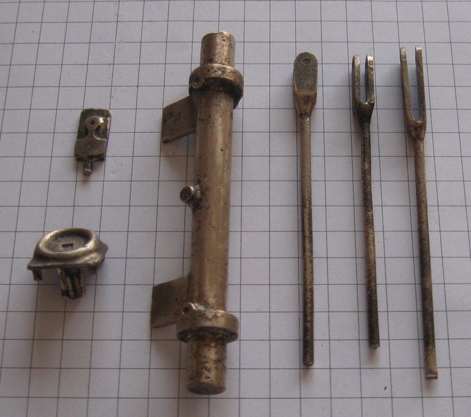
With more complex parts I usually start with wax and cast a metal pattern. Here are the patterns for the steam jamb and old style push pole pockets for the Dulong, brake rods and the boiler pad clamp.


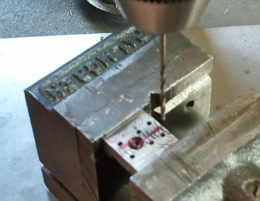
Here are the machine steps for the boiler pad clamps. The casting has a cored hole that is drilled to tap 0-80. Then it can be bolted the fixture shown in the center. The sprue is trimmed and the top is faced in the mill.


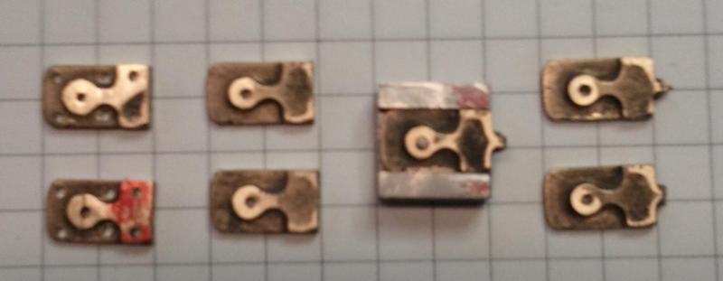
The final step is to drill the rest of the holes.


Here are the steps to machine the frame brace pads. They are for the smokebox brace. The sprue end was chucked up and a light cut to true up the spud was made. The part was reversed and the sprue/chucking piece was cut true and the back side of the flange faced. Light cuts with a sharp tool are the order of the day. And remember which way to turn the hand wheels I stuffed one with a senior moment.


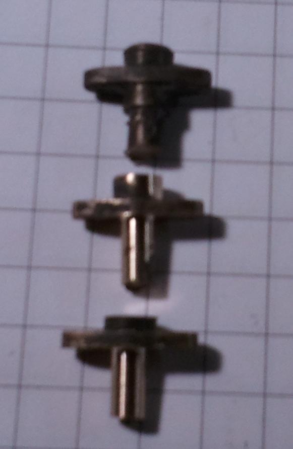
The final lathe operation is to face the spud and tap it 1-72. Cut off the sprue and file the back was the final operation not shown.

The chucking piece I left on the smaller push pole pocket did not really center well with a scroll chuck so I chopped it off and used the 4 jaw chuck. I used the back edge of a tool holder to center the flat sides of the casting.


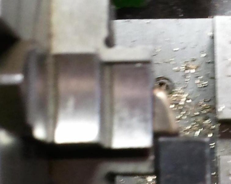
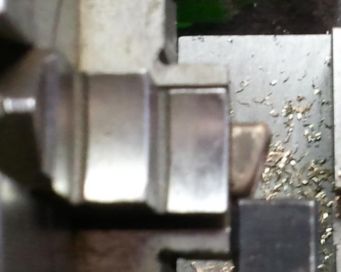
I set the hand wheels to zero after centering the first casting and it was simple to quickly set the other castings square for the machine work. I used a small end mill in the tailstock to cut the counter bore but as it starts on an angled surface slow feed is needed until it makes a full cut.

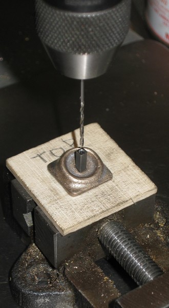
The old style push pole pocket has a square hole for a square head bolt. I used a section of the same steel square square stock that was used for a core and drilled a hole in the center. This was used as a drill guide to for the hole. I used a thin section of plywood and drilled for the sprue and the four pins on the back. The sprue extends past the plywood and is clamped in the vise.


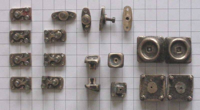
Here is a shot of the new parts for both the Dulong and the Mapleton. I am missing one of the boiler pad clamps but I only intend to add the clamp that has a common rivet with one of the running board brackets. The other boiler pad clamps will be located when the boiler is installed.


Dan
Shayloco Dan