Hi All,
New kid on the Mad Modder block here. I've just discovered this site when trawling for info on CNC conversion.
I've had a Myford VMC mill from new for the last 20 years or so and have been thinking sporadically about conversion to CNC for about half that time. Usually after a tedious session of pecking out profiles from a long list of Excel generated coordinates.

The VMC is quite similar to the generic 6 x 26 that appears worldwide with a range of badges with the exception that it does not have the fine quill feed that virtually all other 6 x 26 machines I've seen.
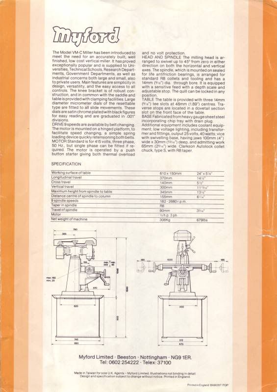
The original data sheet is here
and
I've had a Heidenhain 2 axis DRO on it since new and a few years back swapped the DC motor I was using for get variable speed for a 3 phase 1hp induction motor and a Siemens Micromaster inverter that I run from 10Hz to 100Hz giving a range of 20% to 200% of the designed spindle speeds. The machine has had light hobby use from new and is still in pretty good condition.
A few years back I decided that in order to learn a little about stepper motors and drivers to change the homebrew X feed from a windscreen wiper motor and worm gearbox to a direct drive 3Nm stepper motor (that is about 400 of your strange 'merkin oz-inches
) Currently I still have the 4mm pitch feedscrew and the 3Nm motor is just about man enough to turn it.
My background is in electronics research and development so I tend to be an experimenter using suck it and see iterative methods rather than detailed paper design and build. Well that is my excuse anyway!
Throughout this conversion, I will have to make any parts needed using the target mill supplemented by Myford ML7RB for any turning and milling whilst the VMC is inoperable. This might turn into quite a challenge and as a last resort might be begging/borrowing time in other workshops

As I'm very much a novice in the area of CNC, I'm not proposing to make this write up a blow by blow account of how to do a CNC conversion. There are better threads here and elsewhere written by professional engineers for that sort of use.
I intend to post various sub topics here of my approach on the basis that it might just be of interest and maybe stimulate a discussion.
One such topic is my attempt to balance the load of the knee on the Z axis using a gas spring.
My first task was to estimate the weight of the knee. I wound it right up to the top of the slide, locked the Z axis and released the Z axis feed nut. Once SWMBO was out of the way, I used the bathroom scales to measure the force on the nut which was around 1000kN. Put another way - about the same as I weigh

The vertical travel is around 350mm and I found I could buy an adjustable gas spring with 1200kN force and 400mm travel here
http://www.sgs-engineering.com/gas-struts/range/nitride/adjustable/10mm-rod/gsv10-400These springs are filled with nitrogen and oil and must be fitted cylinder uppermost to keep the seals moist and the gas inside.
The spring is mounted centrally under the knee about 30mm away from the Z slideways.
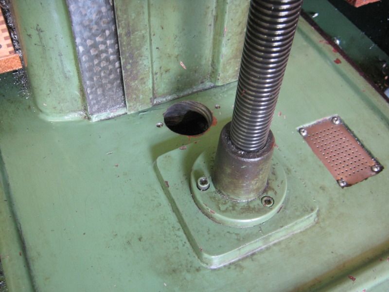
I drill a clearance hole through the cast base and the sheet steel stand underneath with a starrett type hole saw. Pretty heavy going through 10mm thick cast iron and the sheet steel 100mm below. None too pretty result but it did the job!
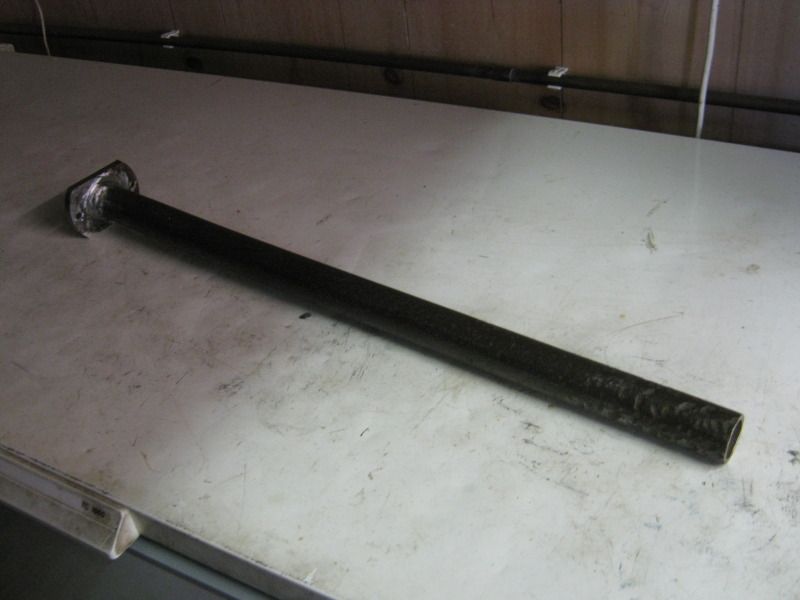
I used a length of 1" iron water pipe welded to a mild steel flange to house and support the piston end of the spring.
and
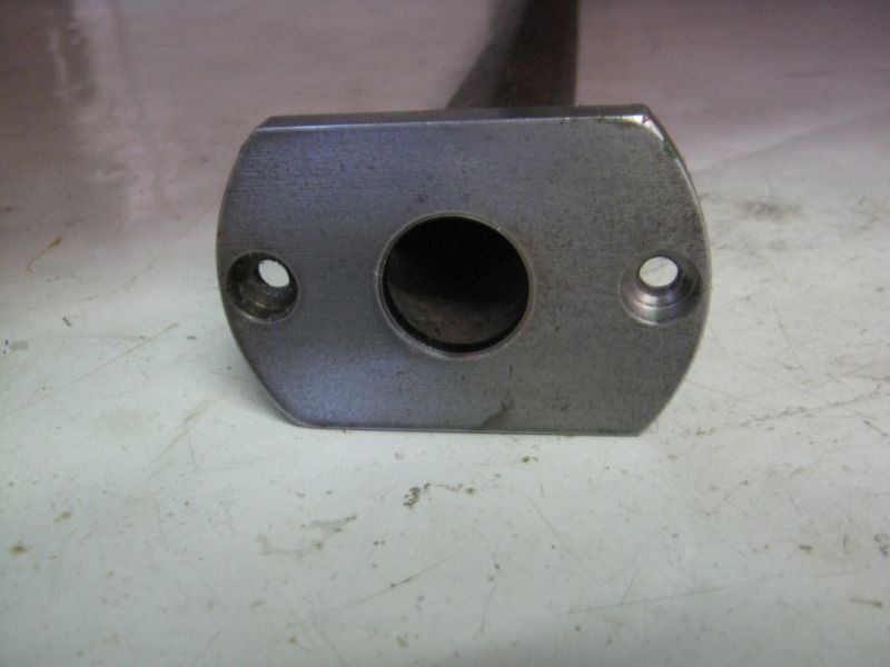
An M6 cross bolt (not shown) was fitted at the lower end of the pipe to support the piston end that was screwed into a short length of 22mm diameter steel bar. The cylinder is also 22mm diameter so the piston end is kept roughly central. Once is had 100Kg of knee pressing down, it won't be going anywhere!
To mark the underside of the knee casting I turned up a pointed steel plug to fit inside the tube flange and lowered the knee onto it - result one centre dot that I could then use a punch to enlarge.
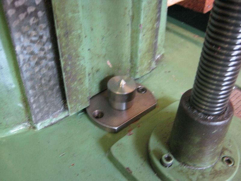
Drilling and tapping the casting M8 was a bit awkward with a right angle drive cordless drill and a small tap wrench with removable tommy bar.
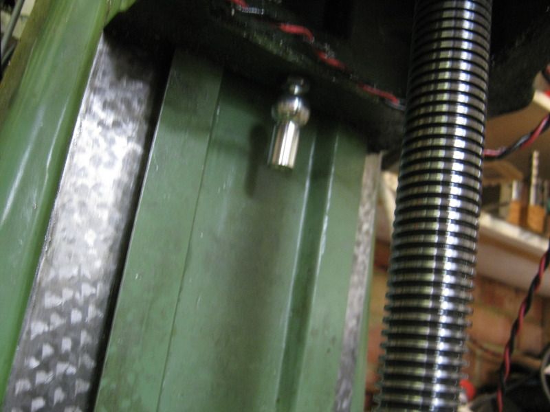
Here is a the ball end fitted ready to receive the gas spring cylinder. There is a choice of end fittings available included in the price of the gas spring.
Getting the spring into position is a bit tricky. uncompressed it is 850mm long before any end fittings are added.
I need to jack the knee up another 80mm above its usual maximum position. So by locking the knee, undoing the nut and inserting spacers underneath, I could use the Z screw to achieve this.
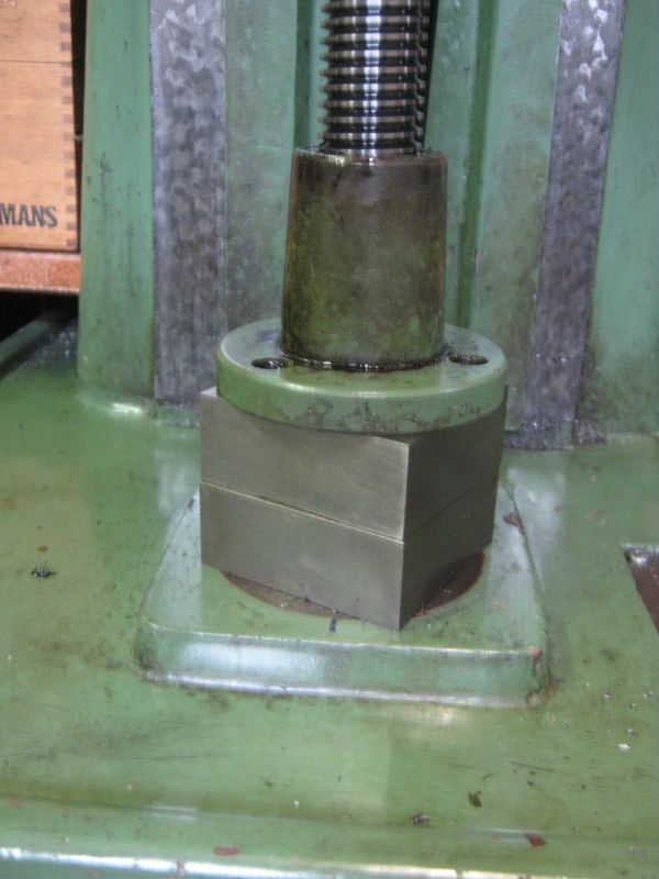
With the cylinder fitted to the knee casting I could then remove the spacers and refit the nut securing screws.
Winding the knee up and down felt most peculiar. Remember we have 1200kN force upwards and 1000kN imposed by the knee. So it take MORE effort to lower the knee than raise it

I then used a spring balance and the feedscrew handle to measure the difference in torque need to raise and lower the table whilst gently letting some gas out of the spring one fart at a time remembering that there is no way back if I let too much out!
I've used these springs before and it is actually fairly easy - a sub one second burst makes a small but measurable difference.
I've now got it balanced quite nicely now and it takes about a 2kg pull at 200mm radius - about 4Nm to move the table in either direction.
My next step is to attach a stepper in place of the handle and see how well or otherwise that works. A 12Nm motor and matching driver are on order from Zapp and some timing pulleys from
http://www.beltingonline.com/ - a new supplier to me but the prices seem good. Lets hope the service matches!
More in a few days with luck.
I hope this is of interest - comments welcome
Bob


