Hi all,
Between a broken down compressor

, visitors from South Africa and an extreme heat wave in Spain time in the shed was short and far between.
The middle sections were finally done.
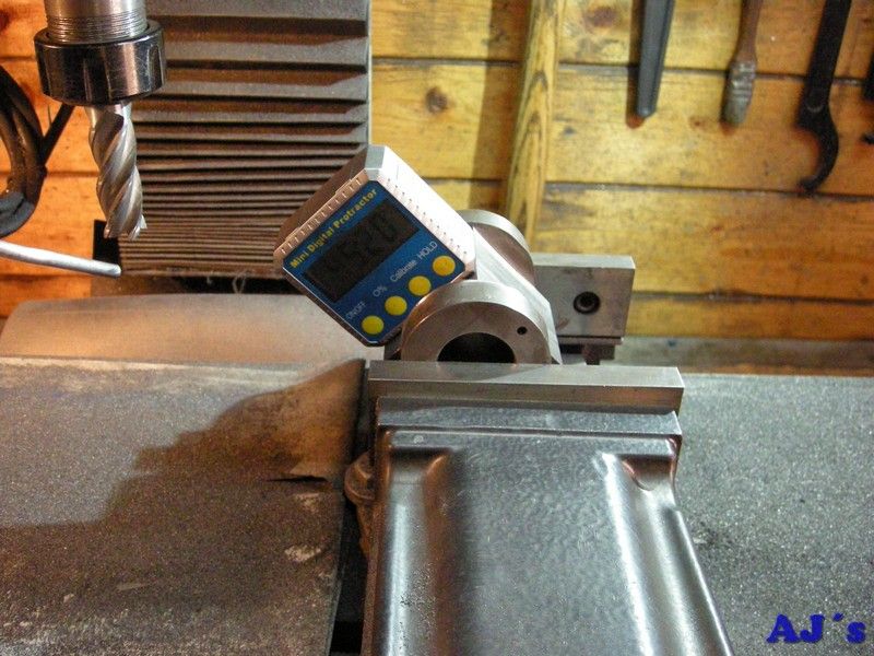
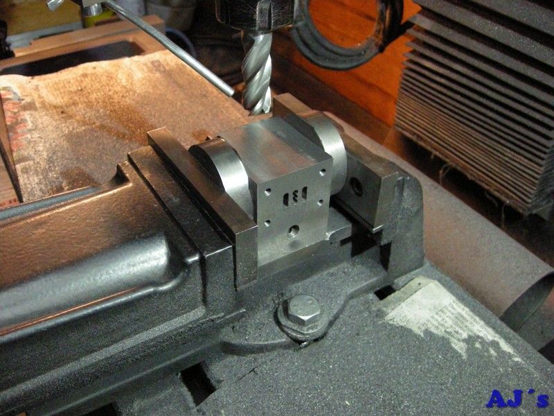 Elmer's horizontal mill engine.
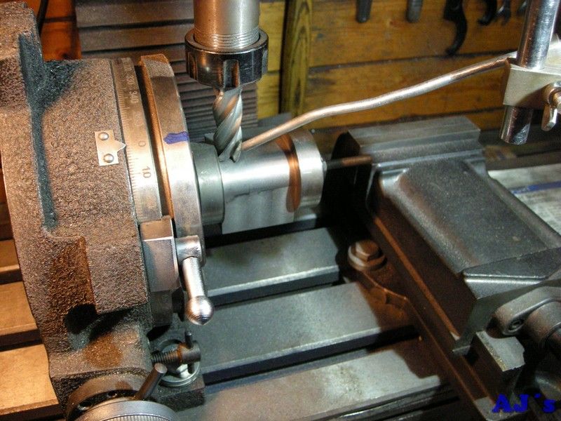
The cylinder was set up at 45 degrees to mill the comer off.
 Elmer's horizontal mill engine.
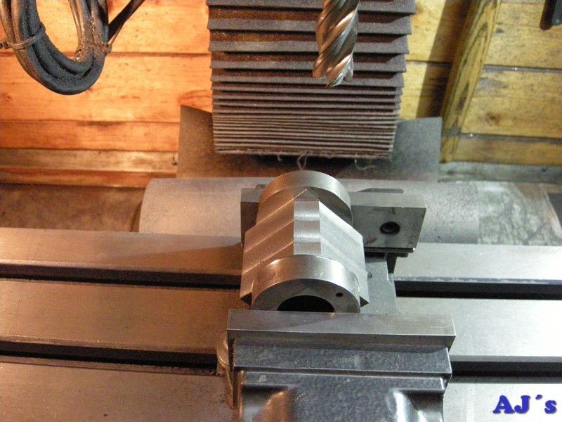 Elmer's horizontal mill engine.
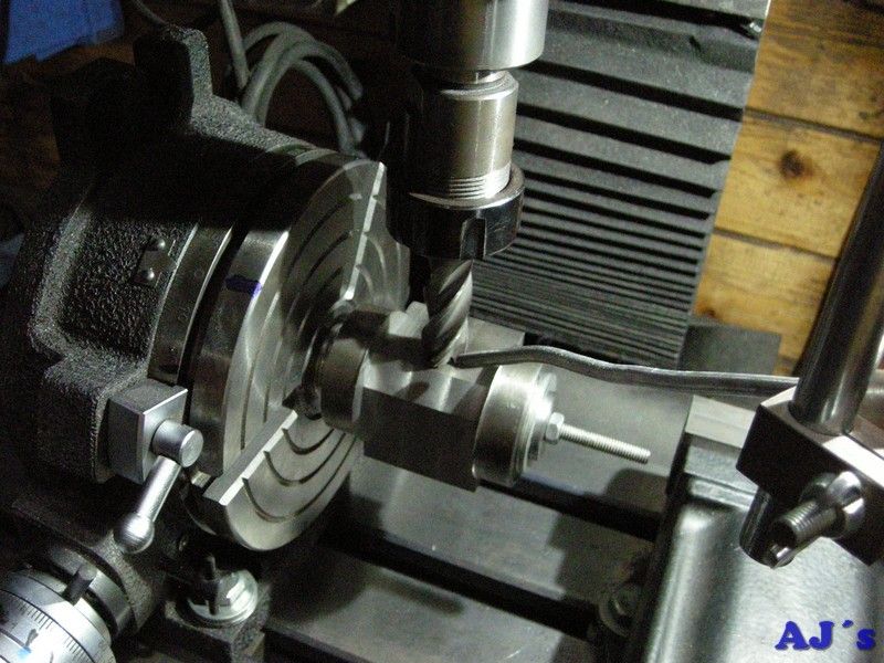
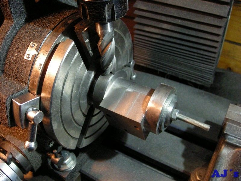
It was moved to the rotab to round over the corner.
 Elmer's horizontal mill engine.
As I do not have any slot drills or centre cutting end mills, had to do lengthwise cuts in facets every one-degree.
 Elmer's horizontal mill engine.
While on the rotab the edge on the round ends was cleaned up.
 Elmer's horizontal mill engine.
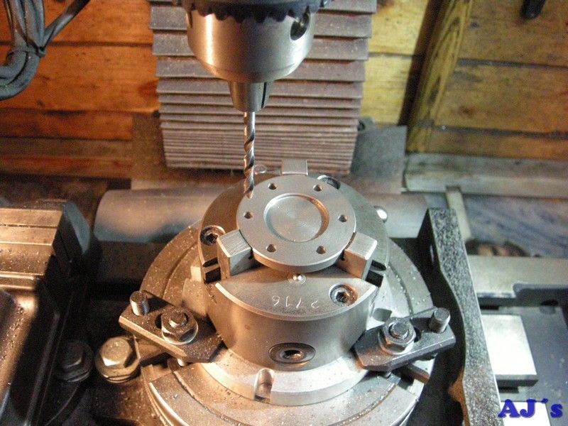
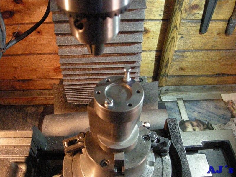
The rotab was repositioned and the mounting holes were drilled in the heads.
 Elmer's horizontal mill engine.
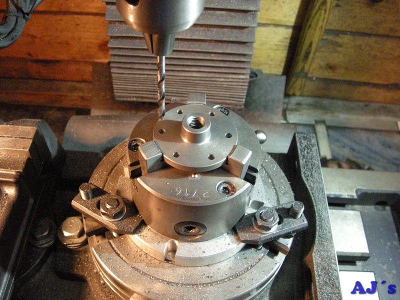 Elmer's horizontal mill engine.
The heads were then used as templates to drill and tap the cylinder ends.
 Elmer's horizontal mill engine.
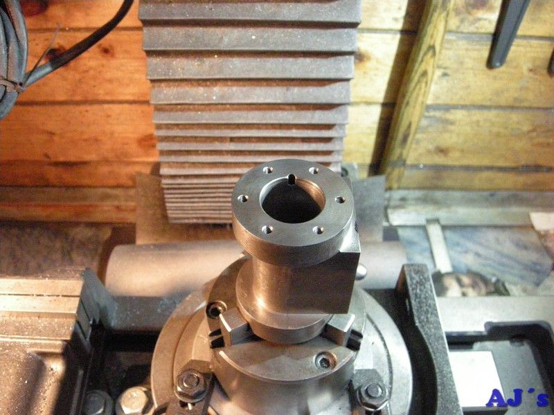 Elmer's horizontal mill engine.
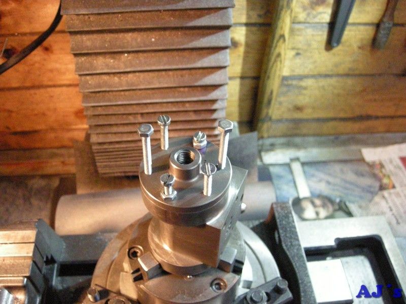 Elmer's horizontal mill engine.
All done.
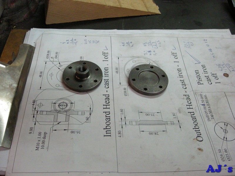 Elmer's horizontal mill engine.
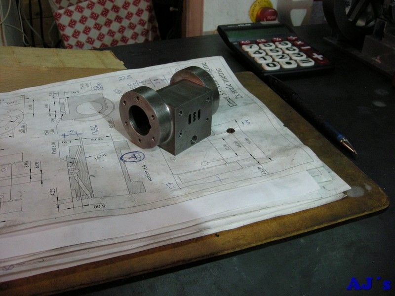 Elmer's horizontal mill engine.
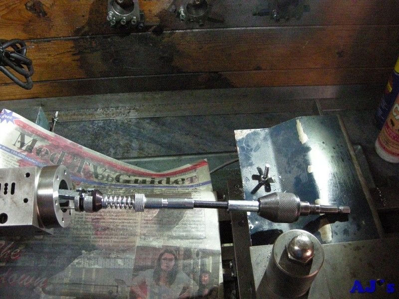
Had to re bore the cylinder as for some reason it was oval. Took the bare minimum out to get it round.
Then used a brake cylinder hone to finnish it.
 Elmer's horizontal mill engine.
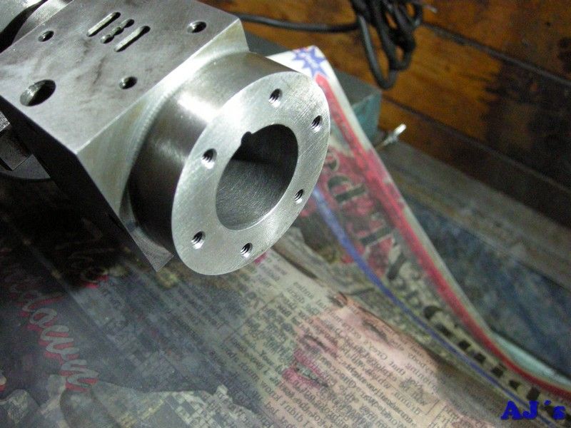 Elmer's horizontal mill engine.
The piston ended up with a bit more clearance than I would have liked, but decided to test it first before making a new one,.
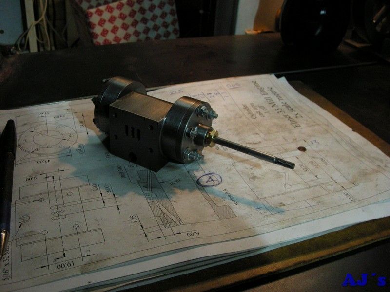
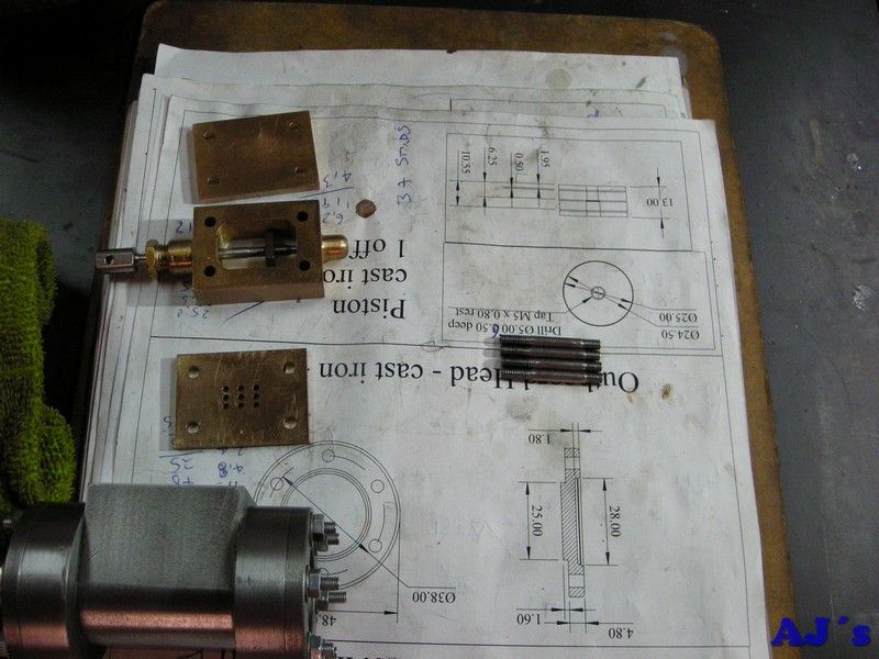
Made the studs for the heads from threaded bar.
 Elmer's horizontal mill engine.
And the studs for the steam chest from bar.
 Elmer's horizontal mill engine.
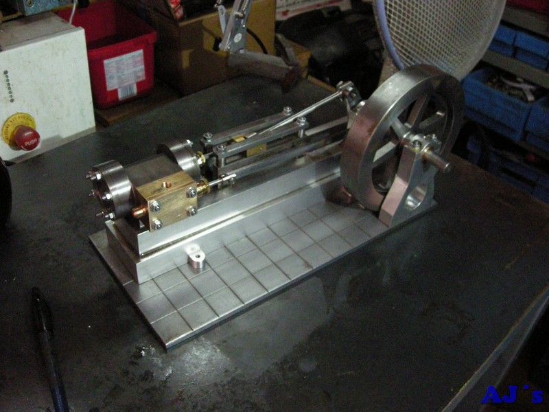
The engine was assembled and I found a small error with the eccentric travel
, somehow I machined it for only half of what is needed. Had no choice but to make a new one making double sure I had the travel correct.
 Elmer's horizontal mill engine.
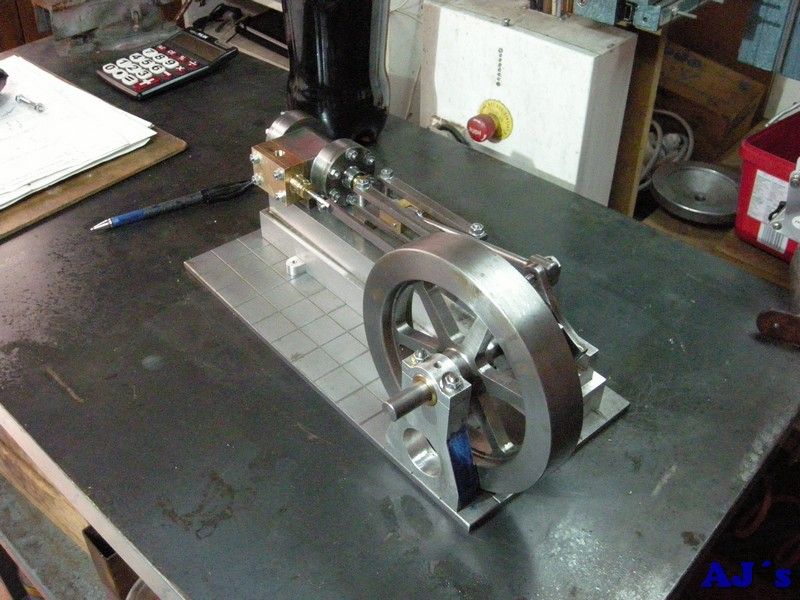 Elmer's horizontal mill engine.
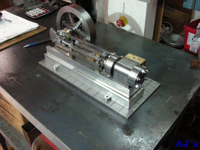 Elmer's horizontal mill engine.And we have a runner
, no gland packing or gaskets but it runs.


Not the best video but here she is.

Need to make some accessories and tiding up a bit.
More to follow.
Cheers
Abraham


