Hi pekka and all,
Got some pics of my cam.
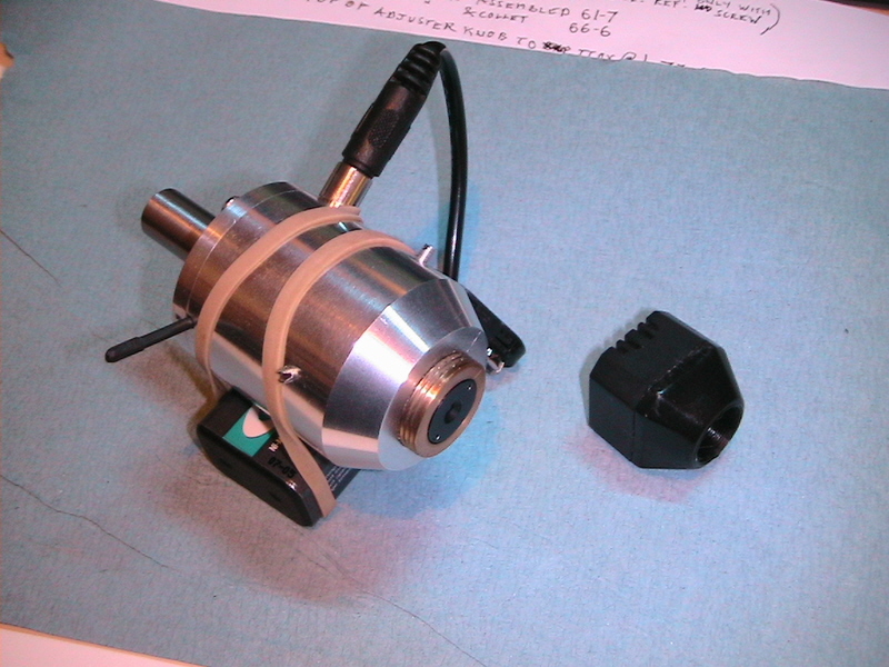
first one shows the general idea. the innards came from the little black case on the right.
I put the brass adjuster in but its not really needed if the case is extended a bit. just trial and error to get the best mag/size/depth of field required. The lens is the one that came with it mounted a bit further away from the sensor.
the sensor board was glued to a chamfered brass ring which is centred with the three cone point screws
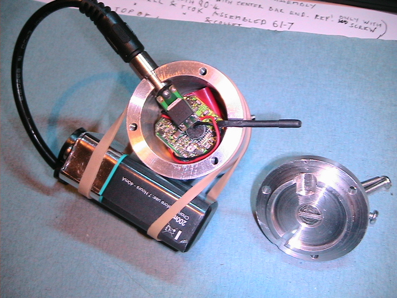
Second is the back.
The body was bored from this side then the lens mount bored and threaded without removing.
The back plate was made and the pin (which locates in a bore not just by the screw) tightened into place with thread lock prior to machining the diameter that locates onto the bore.
Basically I just made it all as concentric as I could, probably didn't need to be so fussy.

The insides. Note the socket on the lead from the camera had a voltage reg moulded into it !
Don't just cut the wires!
The view on a tiny 5inch B&W tv sorry the pic is rubbish this looks a lot better in real life.
The rule in view is 1/2mm Divisions -yes half millimetre so about 40x mag 80mm screen height.
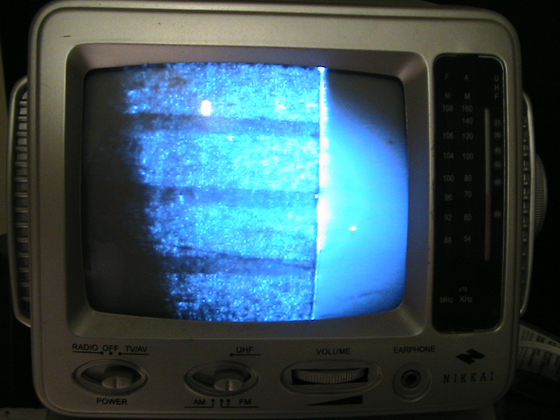
Using this is a bit weird as the camera is free to rotate, its worth putting a big mark on it to indicate bottom of picture.
optical - mechanical alignment is in two parts
Lens to axis - can't do much about it, it's as good as it is.
Sensor to axis set with screws so sensor centre is roughly mid screen.
doesn't seem to matter much.
I mark the screen with an edge in view, rotate 180, mark again split the difference to mark the centre.
Do the same on the other axis.
Now you have a spot the middle-ish of the screen that corresponds to the axis of the spindle.
Hope some of this makes sense.
Cheers.


