Well then, let's get on with another episode of the project, thanks for your input Nick, I took that design from your build log, seeing it as a good, solid and rather easy way to build a good solid big end bearing. I would also say, if it wears loose, as they tend to in steam engines, they can be disassembled and tinned, just in the bearing area, and then scrape fitted and you have essentially a babbit bearing surface, and a few thousandths can be taken up that way. I like their simplicity to make, and the ease which they dissassemble.
finding the end of the cylinder to determine where the main bearings should go, using a wiggler on the back side of the head. I use stainless for the heads of these because it does a very bad job conducting heat, and since the flame hits the head first it is good for it to wait until it's in the cylinder before it cools. Someone, I believe maybe Nick, said turning a taper in the port leaving almost a knife edge for a lip is recomended in the "Poppin" plans, for the same reason. It is rational and logical, and the smaller the engine, the more important the losses are so every little bit helps. I have also turned the heads a bit larger in diameter than the cylinders so they reflect the flame away from the cylinder, and polish their face well on some paper, working up to 600 lapping it on a surface plate. It makes a good seal, and I suspect reduces the temp a bit, but no way of easily measuring without a lab.
With the con rod made out of 3/16ths key stock I'm using a four jaw to turn it down for a #8-32 thread to fit into the brass "big end" previously just tapped. I had to turn a taper in the rear of the cylinder liner to clear the rod as it was touching as the wheels rotated.
Another shot of my die setup, a piece of hex cold rolled, with five eighths bored one end, three quarter the other, and reamed through with half an inch. Four set screws to hold each die in place and a fuel pump rod from a chevy, which is tool steel, hardened and dead on .500, to clamp in the tailstock chuck. The dies sit flush and square with the bore, the four screws allow good adjustment, and I get good straight threads usually, wish I could say I made it, but it came from the kit of a man long gone and his son with white hair before I got to buy it from him.
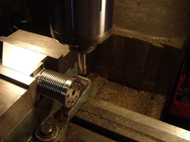
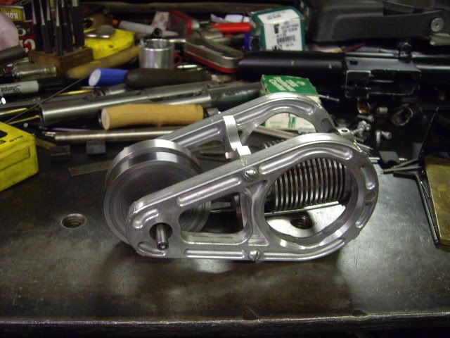
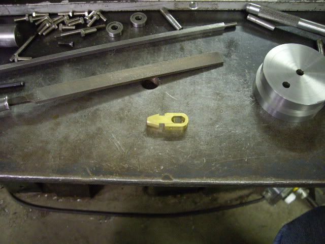
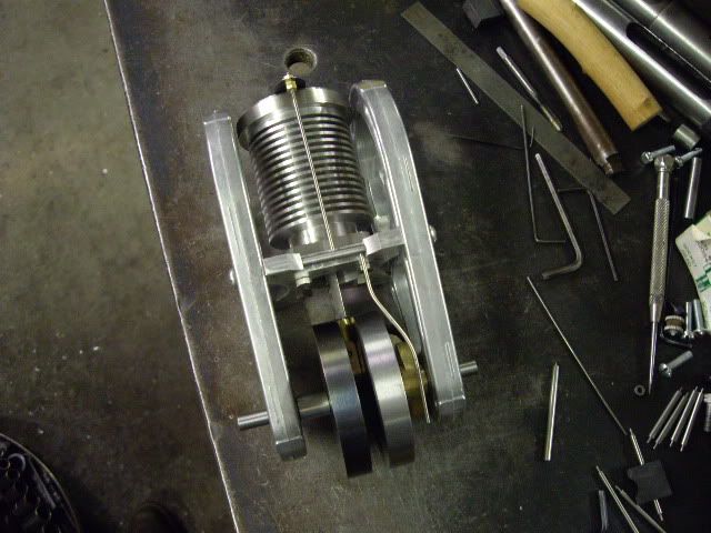
with all the other parts where they were, it was time to find the main bearing position, you can either use math or judgment, but the rod has to clear the bottom end of the cylinder as the crank turns. Having drilled quarter inch holes where the mains should go, I put it on the bench to consider how to set up the valve arrangement. After several hours of un-productive consideration, and running into some interferance between bolts, I decided I didn't like how it looked, or even how it could look, and started looking around the shop for inspiration. I noticed a couple of forgings from a lawn mower engine, rods which move the counter-weight reducing engine vibration. After wiping them off with a rag, the engine having tossed its rod out, I decided they had to be the frame as they looked right, unlike what I'd already made.
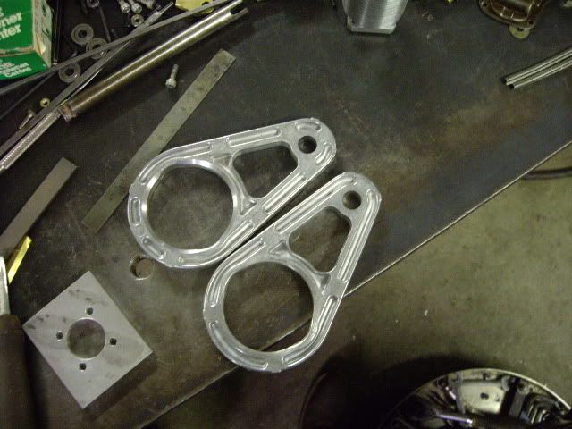
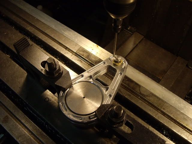
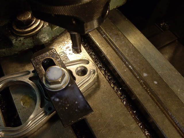
They are matched forgings of aluminum, the large circle is about 2.200 and the small hole is .480 they need a home, as their last one broke open, and they look like engine parts, what more could a fellow ask for? I took a scrap piece of 2.5 steel bar, turned a shoulder to take the big holes, found a bit of distributer shaft which was a push fit in the little end, then clamped the pair on the jig on my mill table, and using the wiggler, lined the centers of the two holes up so I could get the cylinder base mount holes in perfect alignment.
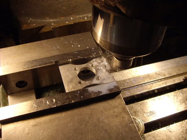
with this, now I have to make the new cylinder base, setting it up for the four cylinder holes and the four frame bolt holes in the edges. The plate will also be scalloped on the sides for bling purposes.
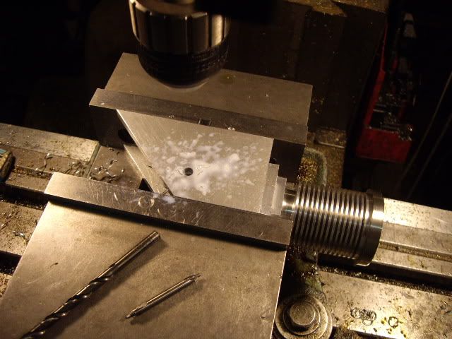
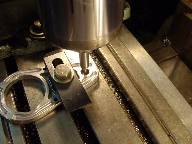
with this done, the next step is to bore the small holes to hold the main bearings. The forgings are almost half an in thick, so I'm boring only .190 deep, the thickness of the shielded bearings.
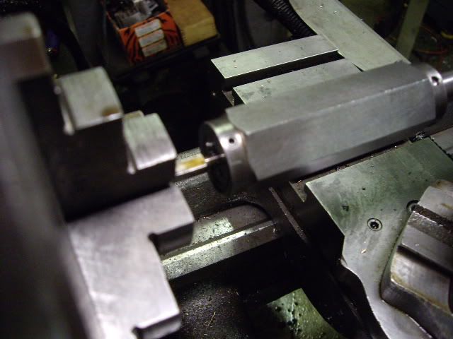
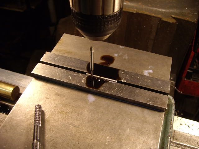
centering the hole for boring
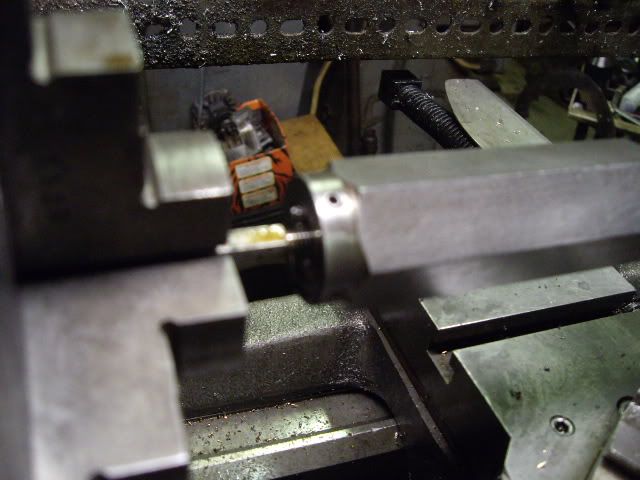
boring the hole
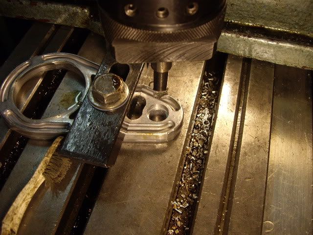
boring the second side
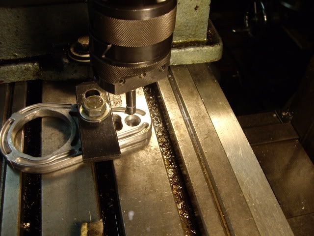
finishing to size, frames ready for the next step
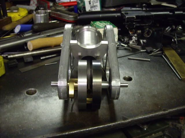
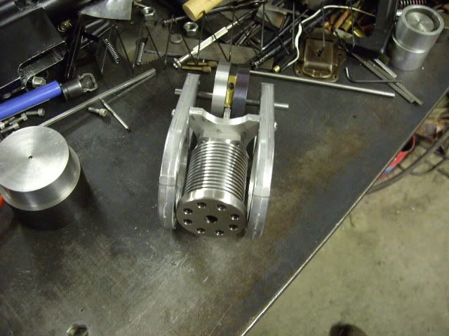
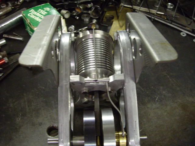
with the bearings fit on shafts an extra cam from my last engine, testing the fit of the frame and setting up end play for the mains
Another shot of the partial engine, ready for valve train work
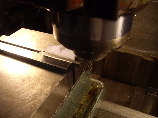
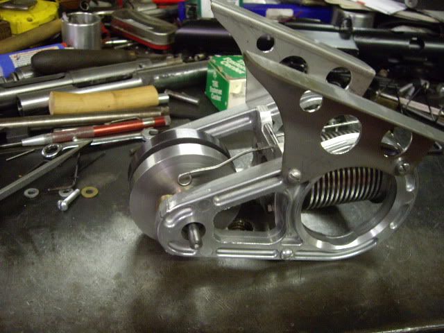
in this position I see a way to run the valve, I just need to mill that fancy curve so the inside ends of the frame mounting holes are exposed, and a shaft matching the i.d. of the tap drill will pivot between the two mount bolts, which can establish fixed end play.
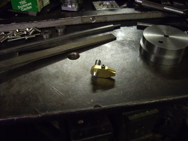
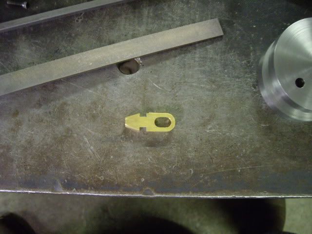
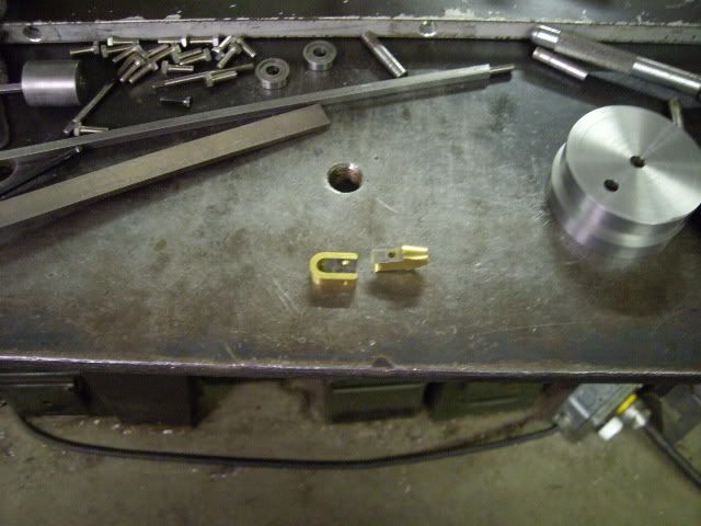
a series of shots of the big end of the rod completed and fit to the crank pin

the rough assembly with the cylinder plate milled for the valve shaft, almost just like in the "Poppin", just slightly different.
I measured the distance between the mount bolt ends, turned a shaft to match the tap drilled holes, and with the intent of having both ends of the valve gear 180 apart, I clamped the shaft in the vise, centered over it, and drilled and tapped two holes for the two levers at #0-80.
Since I changed my frame idea, I had to make a new con rod, to match new dimensions.
With the valve shaft in place, it is easy to take some 1/16th drill rod, thread both ends for a valve rod, to carry a .006 in piece of feeler gauge, and thread one end of the leftover drill rod, and watch the valve movement with the cam pushing merely against the drill rod, bent to bear on the aluminum bronze cam. It worked so well I decided to make a judicious cut, then carefully bend the end of the rod around a piece of shaft, and have a round end of rod bearing directly on the cam, and in setting the timing, found the cam fits well with this arrangement, and is a very light and easily moved valve set up.
I kind of sort of want to put this engine in some sort of vehicle maybe, so while it is complete except for mounts, I found some scrap pieces of stainless with a bend, and cut mounts out of it, for it to stand on for now.
Feet straight up, resting
lying on its back, you can see the loop which is the cam follower
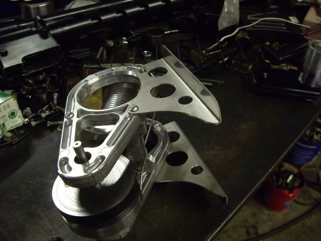
on it's side, showing all.
Well, got to get to work, somehow I didn't get a shot of it on its feet, but I'll be posting a video tonight if I get the chance. Thanks for looking, hope you enjoy it as much as I do. cheers,

mad jack


