Well... its been a few days since I have uploaded some pics, so, here you go...
Let me first start off with a video of how you should listen to that little voice in your head when it says.. "be ready to grab it if something happens"
All is well... camera fine, engine fine... clamp not fine, extra tight now....
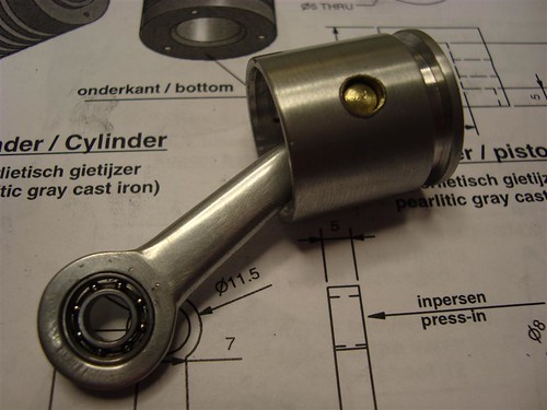
Anyway, I got the piston and connecting rod cut and assembled. I am going to use a Viton o-ring for a good seal, but I might not need it... it seems to have decent compression now... we will see...
I had to make something shiny...

I used a hard brass rod for the wrist pin. Jan suggest steel, but that might grove the side of the cylinder, so brass works good. Not enough compression to worry about sheer... The bushings are brass as well. The oil blow by from the fuel mix will keep them good and lubed.
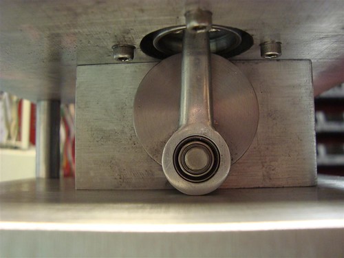
Piston installed. What a pain... I see now why Jan has only three bolts in the bottom of the cylinder, you can then take the cylinder off to remove the piston. I have four and one is under the main bearing support, so to remove the piston I have to take the engine just about completely apart. I think on next assembly I will forget to put in the hidden bolt... oops...
I added some footsies. The center spacers were removed and drilled and tapped 1/4-20 on the bottom for some threaded rod jam locked into the 1 1/8 38mm long feet. I will get some rubber to glue onto the bottom.

The flywheel supports took forever. If I had it to do over again, I would line drill them out when fully assembled and trued on the lathe. I oversized the hole on the flywheel so that it is only supported by the two aluminum end pieces. It is within .0005 eccentricity and .001 wobble. I could probably get that out with bolt tightening, but its pretty close...

Now for something that I have been dreading... the manifold. I would like to say it came to me in a dream, but really it dawned on me what to do while watching Survivor on Wednesday. The engine usually lives on the coffee table when we are not in the shop, so I have time to stare at it and design.
I decided to have the intake and exhaust come out the top for symmetry and then I don't have to cut into the side of a curved surface for the intake.
The stock was just a piece of 1/2 x 3/4 6061 rough cut on the band saw, drilled for mounting holes (I used two, plan only one) then indicated on the lathe.


Then I turned and grooved. Turned out pretty good... I was worried that it might grab and get thrown because there was VERY little on the inside lip to chuck onto.

I then cut out the extra on the top sides and drilled the holes for the muffler and intake (to be made today)

And now some videos for your viewing pleasure...
Piston and crank. Nothing hits, but it is reeeaaalllyyy close.. about .5mm gap between the connecting rod and the base. Might have to modify if it starts rubbing when at full speed...
Clamp REAL tight and plug removed so there is no compression.
Exhaust valve held open with cam, plug in.
More to come... thanks for your constructive comments and suggestions...
Doug


