A few months ago I did a little job for a chap who was repairing his car. The car is a 1919 Humber and turns out to be his 'new' car. His 'old' car isn't really a car, and when he asked me to make a pair of new front stub axles and rear brake 'drums' for a 1898 Clement quadricycle, I thought he was having me on, but no.
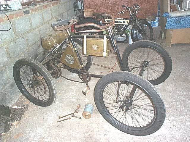
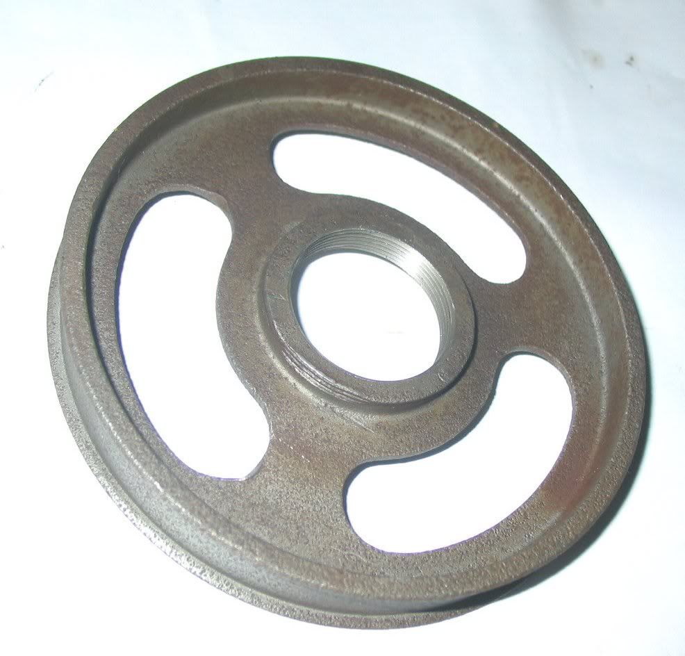
The original drums are nice, very fine iron casings, but both left and right had cracked. We decided to make new ones from steel, not such a nice bearing material, but not prone to cracking and as they are not conventional drums we don't think this will be a problem. Although they are 'drums' the brakes are an external brake band, lined with leather rather than (now) conventional shoes and Ferodo.
Here's the original drum
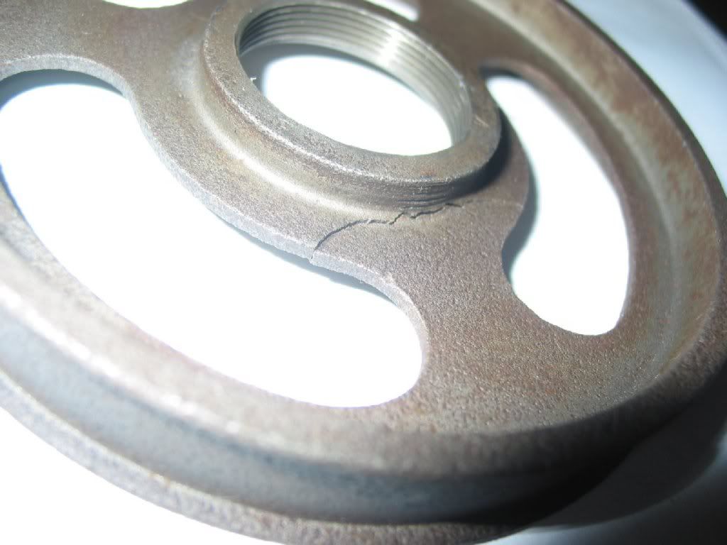
and a close up of the crack
This is one of the blanks being roughed out
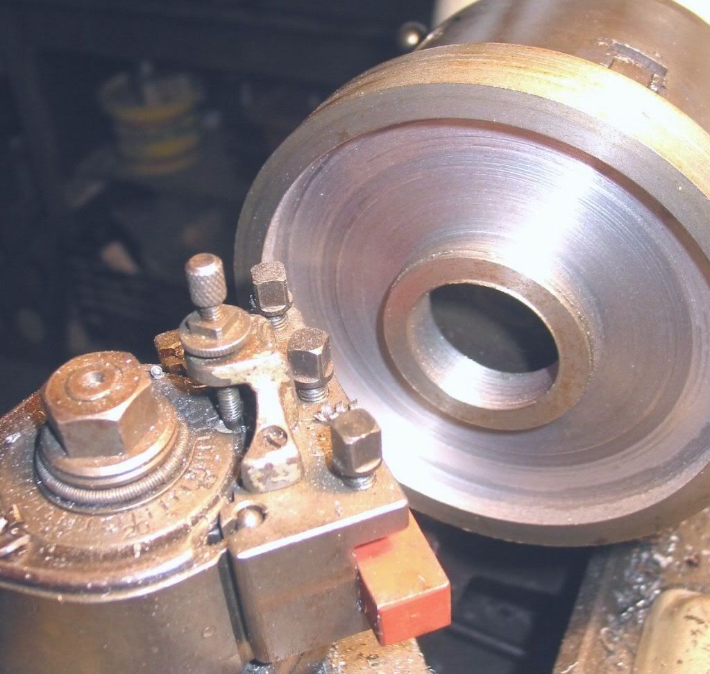
Easy and small enough to do on the small lathe at home, but there is a twist in the story. It would have been easier to keep them all true by cutting the threads last, but the blanks were given to me ready threaded to match the hubs, with no internal shoulder as a reference to clock to, just the thread which is how the originals are made. So I needed to finish turn them on a suitably threaded mandrel, however.... the right hand drum is screwed to the hub with a left hand thread to prevent it unscrewing in use. No bother sorting a mandrel with a LH thread, but how to turn it as the LH thread would unscrew off the mandrel? Soooo, do it all backwards. As the small lathe at home has a screwed-on chuck which would probably have unscrewed running backwards I went round to the workshop at my folks' place and used the bigger lathe with a cam-lock chuck mount, ran it backwards and cut on the far side of the centre
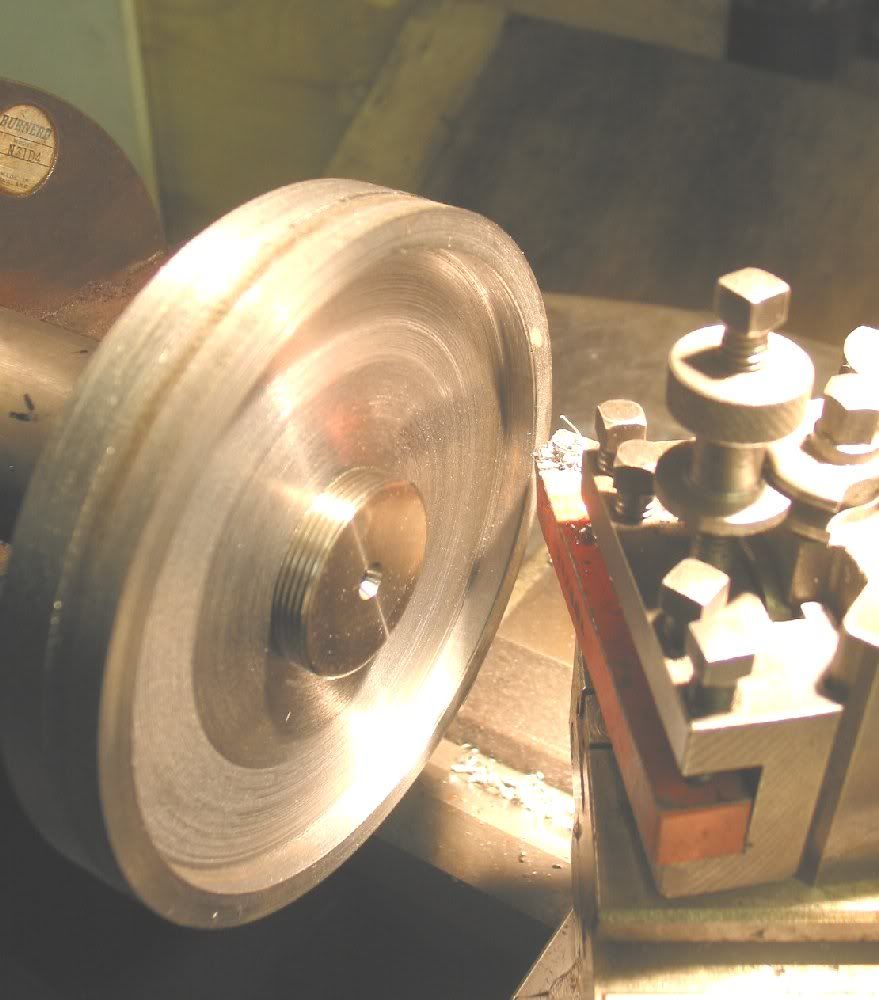
This is perfectly reasonable, but feels seriously wierd! The compound slide was twisted just to give it clearance from clobbering the tailstock all the time while manoeuvering.
More peculiar still, to true the outer surface of the rim and produce the side flanges, keep running backwards, but turn the tool upside down.
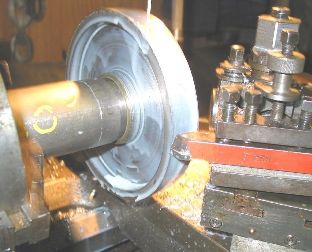
which is even wierder
I now need to bung them on the rotary table to knock out the slots in the webs to make them look like the originals. I'll post some pics when I've done them.
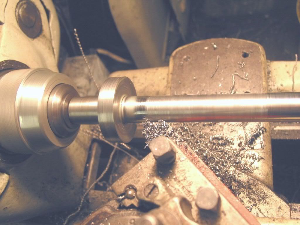
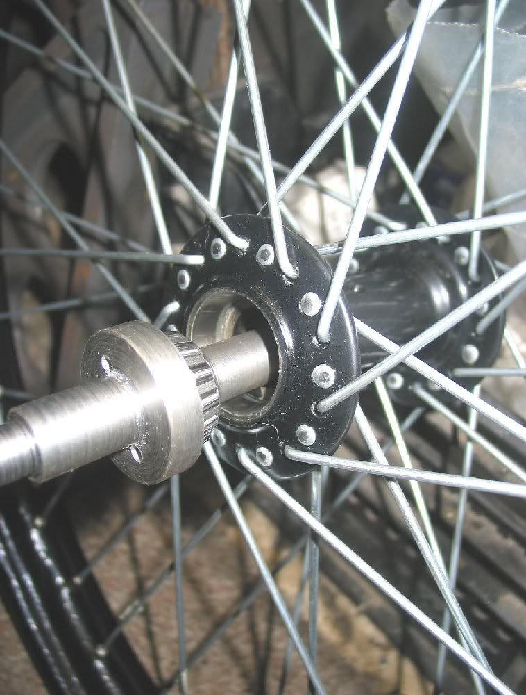
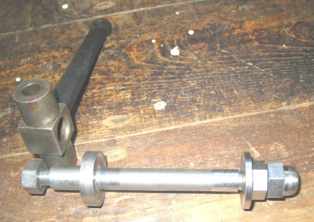
The axles are a straight forward turning job in AISI4130 (En19 for we Imperialists), again with left and right hand threads according to the side of the machine and a small change in design to use modern taper roller bearings instead of the horrid bicycle-style cup & cone grit-grinders of the original.
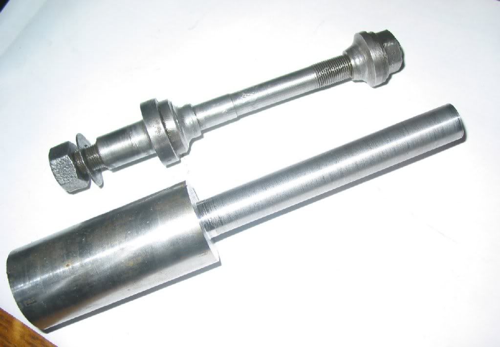
I also extended the shoulder slightly to make a dust seal, not up to modern standards, but the best I could manage while still keeping it looking right. I have wondered about some felt wipers, but I think it will damage the enamel on the wheel and as there is only a very narrow land (less than 1/8") I doubt I could get felt to stay put anyway.
The two small holes in the shoulder/flange are to allow the bearing to be punched off the axle. They will be covered by the steering upright once the axle is fitted to upright and invisible.
The last part was to make a set of new nuts. The inner nut has an integral flange as a dust cover, mirroring the profile of the shoulder on the inboard end of the axle. I had to do the acorn nuts free-hand (note to self: I really must get round to making a radius/ball turner), but they look OK and in keeping with the rest of it all.
I ended up with the best part of a bin-liner full of swarf, but that's what the machines are for I guess, making swarf.
Richard


