Tonight's episode: Shafted!
So... cast (sorry

) your mind back a few days, and I showed you this upside-down picture of the headstock foot (before I completely broke it):
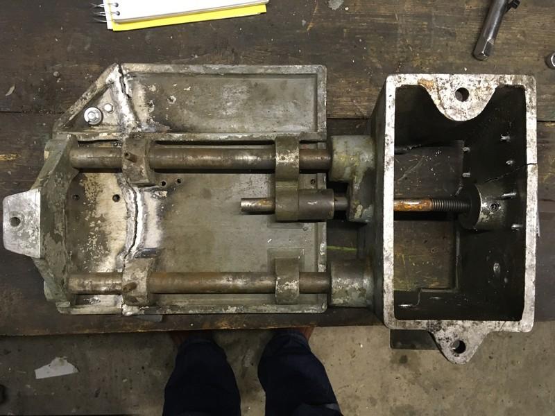
Observe, if you will... the central shaft, which (you can almost make out) has a 3/4" hex head at the front (right-hand side), goes through a boss, there's a threaded section, then the shaft continues through the back of the foot and into an elongated boss on the pulley/motor plate. The other two shafts, one of which looks bent (but I don't think it is) carry the weight of the motor/pulley. I'm pretty sure that the "Y" piece at the far end (left) bolts to the bed so the foot isn't actually expected to take the entire leverage exerted by a heavy motor; although that's actually the first time I've noticed the hole in it's foot!
So... here's the shaft after a painful extraction from the casting:
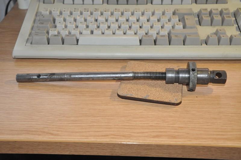
You'd expect, looking at the above, that this would be a 2-piece shaft... except the OD of the threads is the same as the OD of the shaft... so how on earth did they do it?!
Simples, when you see it:
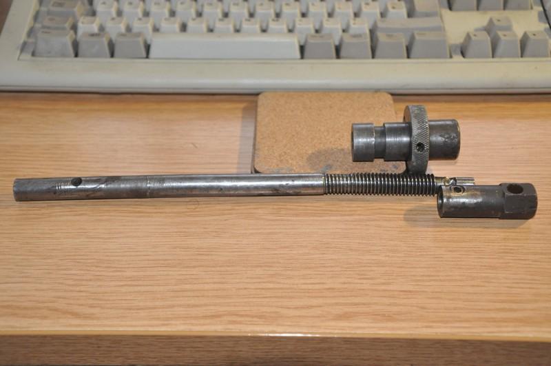
Yep - THREE pieces! The main 1/2" x 10 1/4" shaft, with a threaded section, and a relief on the end. The part that fits in the boss, and then a separate sleeved section carrying the hex head. Please excuse the condition of the threads by the way... the only way I could get the boss section far enough up the shaft to remove the hex end was to put it in the Edgwick and effectively destroy the threads.
Note the two "divots" in the shaft: The far (left) end has broken off, but one assumes it was a large screwed-in affair, with a protruding head. This engages in the "boss" under the motor shaft, and provides the "quick screw" action to tension/un-tension the belts. The entire effort of that thread/unthread - which one imagines could be quite considerable, was carried by the small grub screw passing through the outer sleeve and into a hole in the shaft. No wonder it looks more like a volcano crater than a nicely drilled hole! TO my mind, this is probably the weakest part of the design, and I may try something a little more robust when I rebuild this part.
Finally - the adjuster nut. This is the clever bit (in my opinion!) - it's designed to rotate in the headstock foot (hence the C-spanner pin holes), by "tightening" it (clockwise) one loosens the belts a bit, and "loosening" it conversely tightens the belts. So a nice easy way to take up any variation in belt length if you had to change it, or as it stretched over time. The 2 1/2" thread length also allows access to the hex sleeve grub screw, without having to drill any unsightly access holes. It's all about the aesthetics! I assume that, as it's knurled, it's supposed to be easy to turn.... mine was wedged most thoroughly in the hole though, and required the arbour press to remove it. The reason:
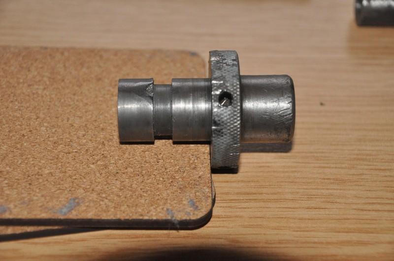
The grub screw, which also acts as a retainer to keep the adjuster nut in place, has bashed its way into the backside of the slot it's supposed to run in, so hard that it's gouged half it's own diameter out. Further evidence that this lathe fell over backwards. Possibly over a cliff. The burr raised is what made it impossible to turn, or withdraw; and obviously using the press will have damaged the casting (it pulled a flake off the front, I imagine it's also left a huge gouge in the bore. Nothing a bit of emery won't fix). I did file it down a spot, to see if it would slip back in, but it was still resisting, so I've not forced it.
So - my plan:
First - make a new shaft, which is as easy as pie. I'll put a phosphor bronze insert in at the end to engage with the quick screw tensioner.
Now... here's where I'm undecided. I quite fancy making a new sleeve, and using the die sinker, erode a hexagonal hole into it. THEN drill/tap for a grub screw. That way, the forces on the shaft, when tightening, will be taken by the hex that I'll cut on the end of the shaft, instead of by the poor grub screw alone. Also, it gives me an excellent excuse to finally use the spark eroder for an actual job - justifying the few hundred quid I spent buying it!
Last but not least, I'll weld up the damage to the adjuster nut, and clean it up on t'other lathe. I can either turn the end off a grubscrew to give a smooth running surface, or even cut a small fozzy-bronze block to ride in the slot. It won't stop it getting mangled if the lathe falls off another cliff.... but it might make it easier to take apart afterwards!
I also need to make a new tailstock nut. No pictures of that, 'cos it's literally very ordinary. The only thing that took me slightly by surprise its it runs on a normal 1/2" Whitworth thread, and not an Acme screw. Still, that should make it a tad easier to cut the threads.
Right, I'm off to haunt eBay

, I need some fozzy bronze


