Hi all,
Got so involved in building the engine I did not do any updates in a while.
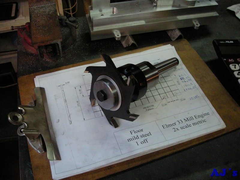
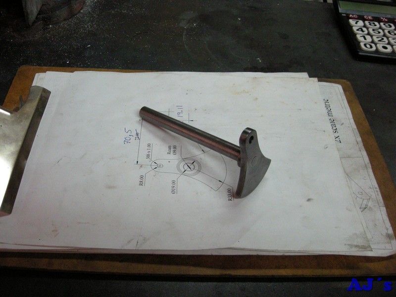
Finished the arbor, to be used later.
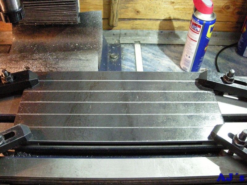
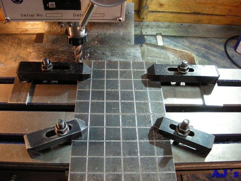
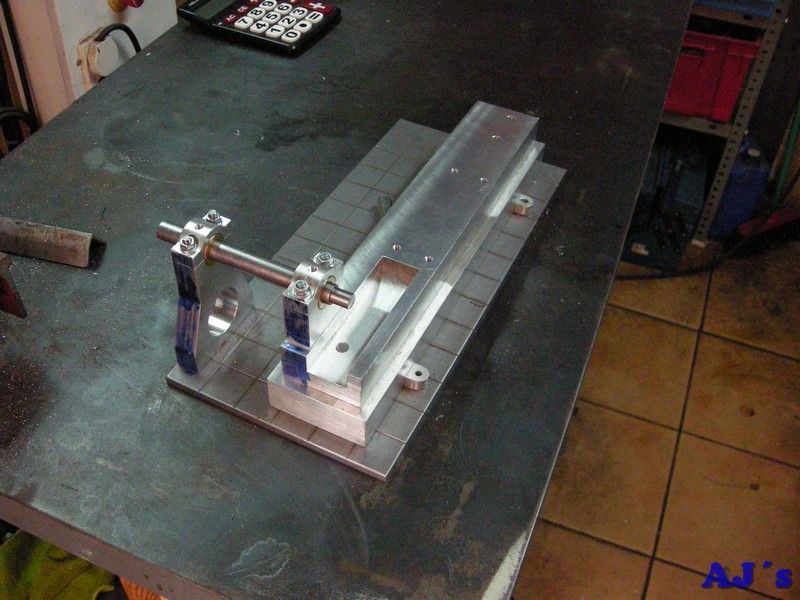
Mounted a piece of 6mm mild steel plate on the mill and machined the long sides parallel and to size. Then using a spot drill some grooves was engraved lengthwise.
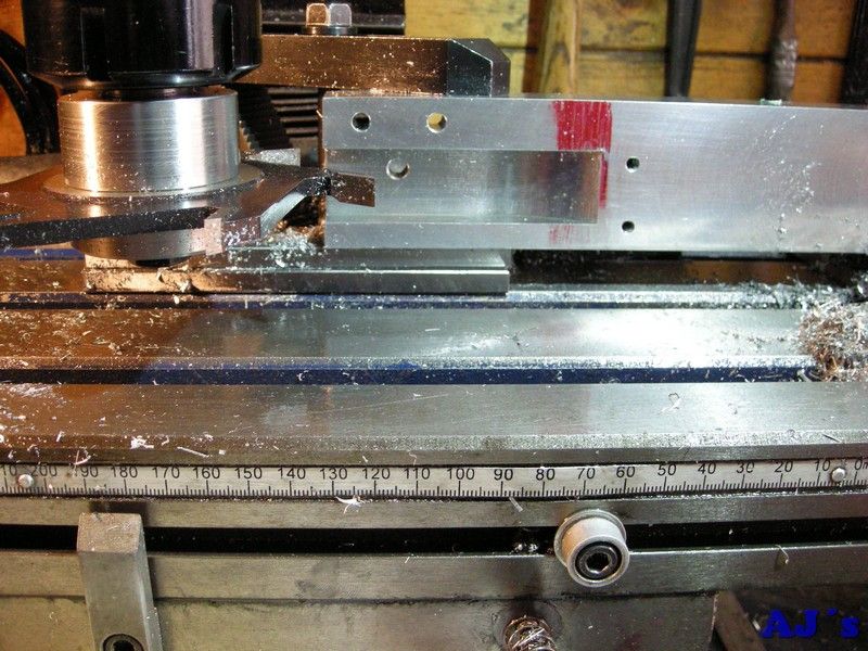
The mill does not have enough cross travel to do the sides, so the work was rotated and the one end milled square. Half of it was then grooved.
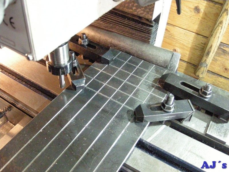
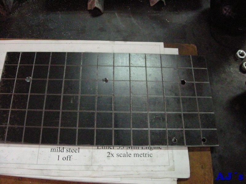
Then rotated 180º and the last groove picked up to finish the grooving to the end. The end was then milled square and to length.
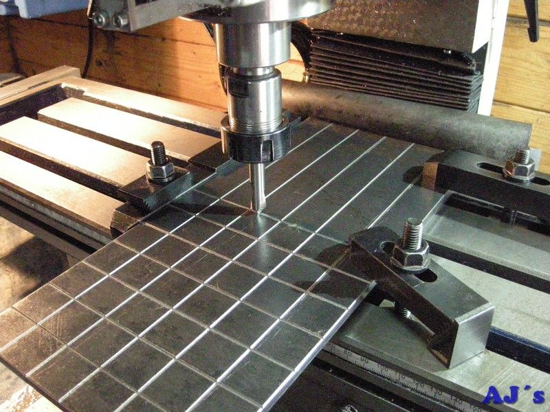
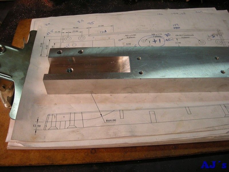
The plate was flipped over and all the hole drilled and counter sunk.
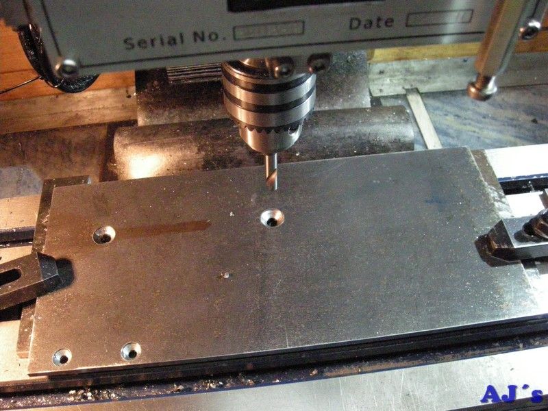
All done.
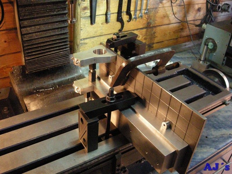
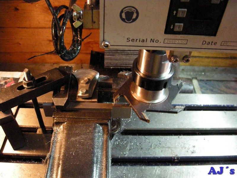
The base was mounted on its side.
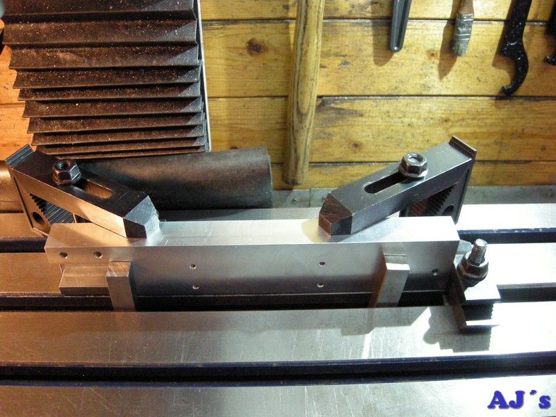
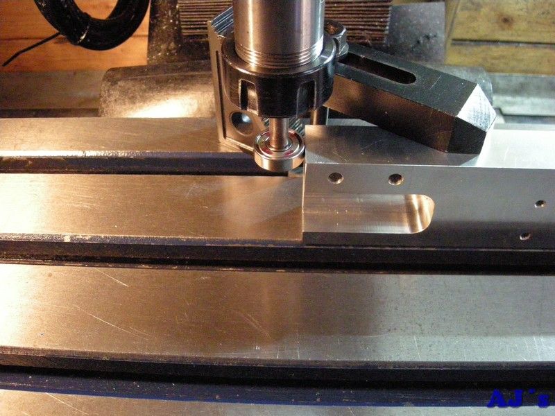
The side and face cutter was used to finish the cutout for the crank and conrod. As the cutter has only a few teeth this was very slooow going.
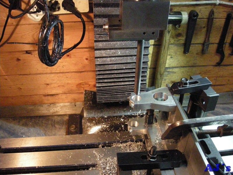
With everything assembled the bearing posts was first drilled and taped for lubricators.
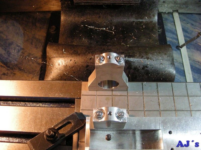
The assembly was then mounted on its side for boring the bearings.
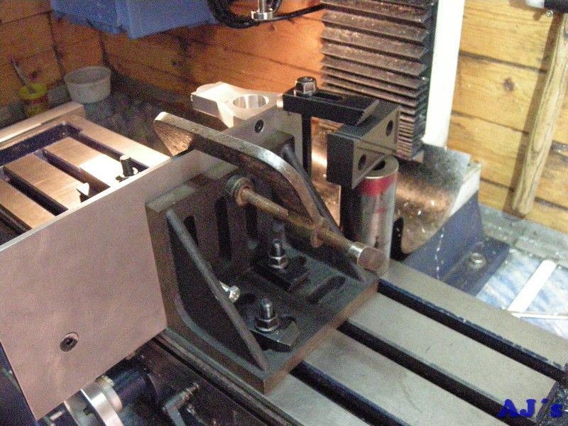
Had to use one of my lathe boring bars to reach down both bearings.
With the bushes and a few bits added.
I did not like the fit of the bushes so they were remade.
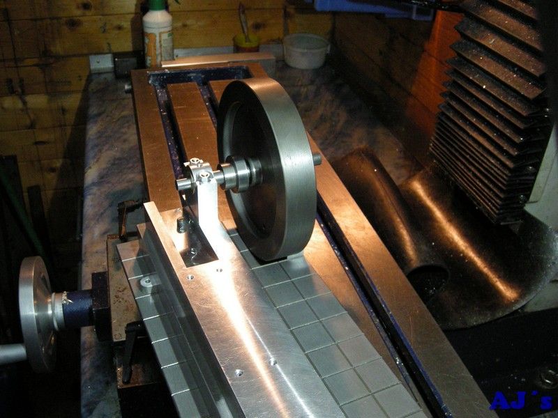
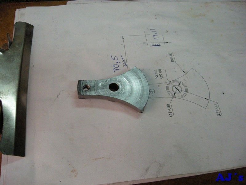
With the help of a fixture the crank web was mounted on the mill.
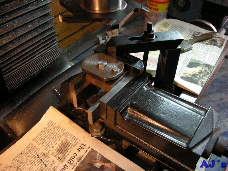
The side and face cutter was then used to cut the curves on the crank. Can anyone notice something odd in this picture?
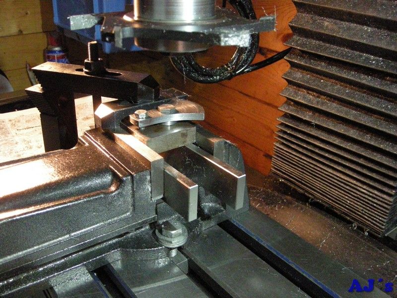
The cutter was mounted other way around and the mill ran in reverse to get a better cut.
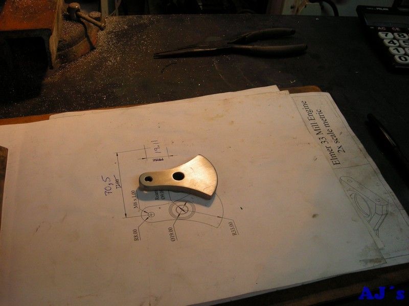
Hot off the mill.
After filling the end and a bit of a cleanup.
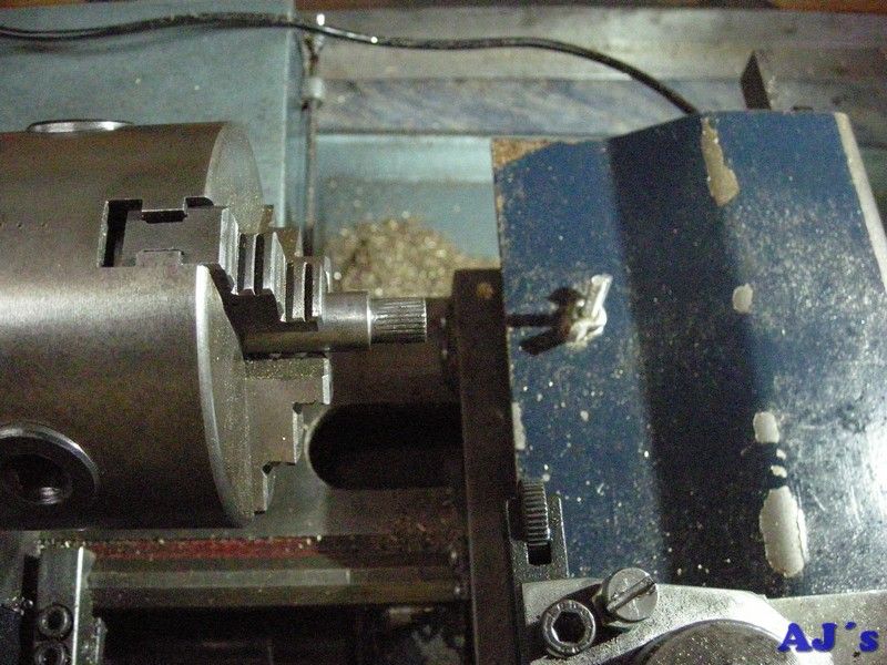
The end of the crankshaft was given a light knurl.
The crank was pressed on and tin soldered.
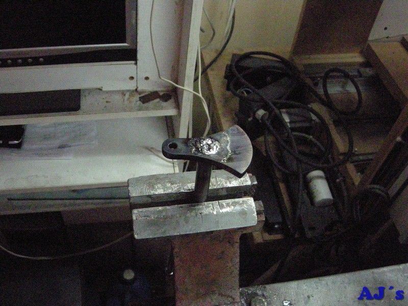
Cleaned up.
Cheers

Abraham


