Stew, Cheers mate

Thanks David

I have still have a lot to learn from Stew

- but the fiddly bits seems to be getting easier to make

Cheers John

- nothing clever about it though; just me being lazy

- it doesn't turn out perfect this way; just "good enough for now"

Thanks Dave

- I was hoping to be a bit further along, but some "life" happened in between


Yesterday was a dead loss in the shop; "work" work all day interfered...
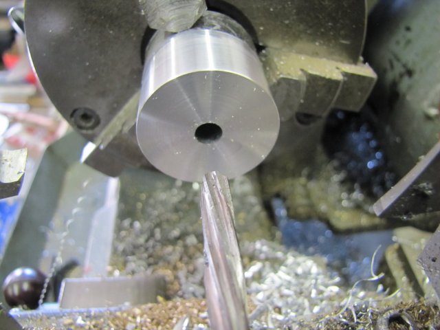
This morning I started off with the crank webs - digging through my stock I had a choice between aluminium and bronze in the approximate sizes needed. As the flywheel web is aluminium, I decided on the aluminium to match it; all the linkages will be brass anyway, and I like a bit of contrast. Cleaned off, and drilled and reamed to 6mm:
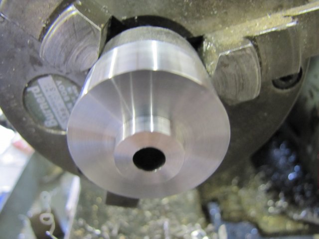
Next, turned the step on the first web:
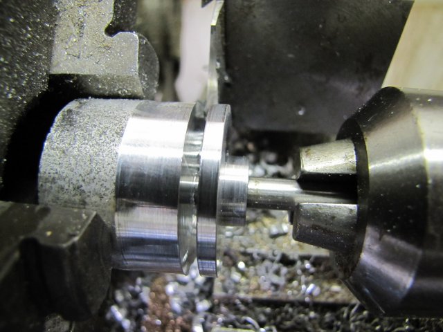
And parted of with a bit of oiled 6mm rod in the tailstock chuck to both help support and catch the web:
The second one followed - using the same measurements. I'm slowly starting to get better finishes on parting cuts - it still looks horrible though - I wonder if it's possible to get a really smooth finish on a parting cut ? :
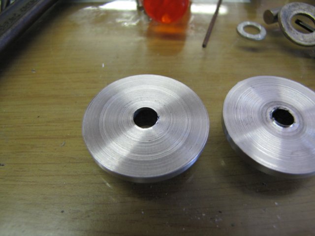
I'll just keep on trying harder

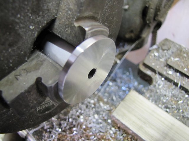
Cleaned up the ugly parting marks:
The webs must be made as a left and right-hand version, and to prevent binding on the engine later on, their crank offsets must match exactly - so I shoved a bit of rod through them held back-to-back, and clamped them together and clamped them flat on the mill vise:
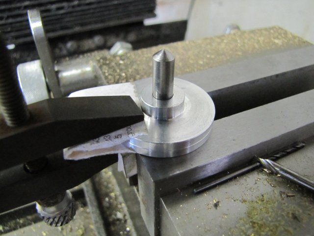
Then I used the edge finder to locate the center line in Y and also the X edge of the pin; then I just dialed in the hole position on the X handwheel - it takes a simple bit of work on a calculator to calculate crank throw - (half the pin thickness + half the center finder thickness) and dial that in

A quick spot with a center drill, and drilled a 2.5mm hole to thread M3 later:
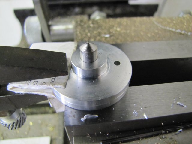
While I was busy drilling holes, I drilled the 2.5mm holes to tap M3 for the grub screws (set screws) as well:
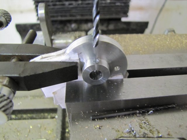
After sitting down and playing around with the set of M3 taps, I had the finished webs:
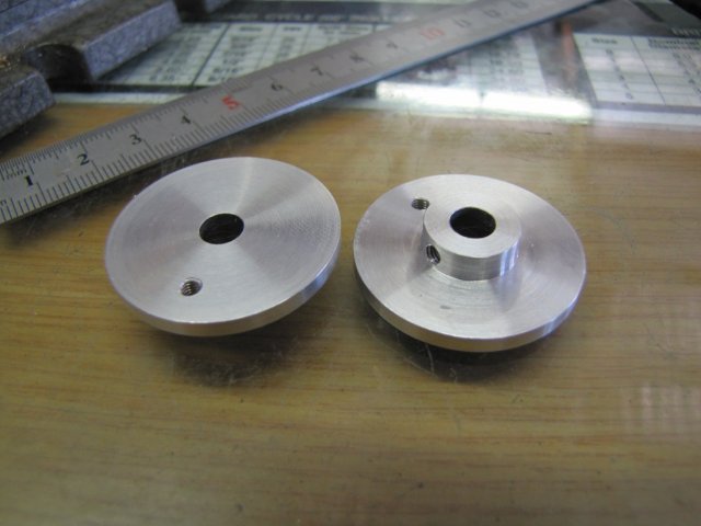
There's some scuff marks on them; those I'll remove at a later stage.
I did a bit more paint work on the columns, and COMPLETELY stuffed it up


:
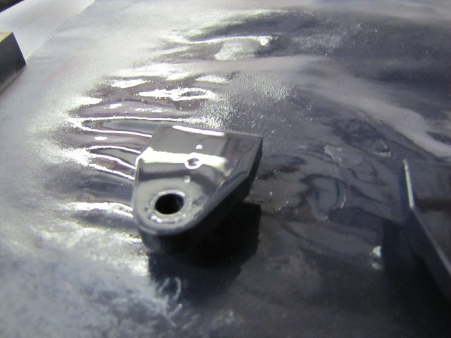
Hopelessly over-sprayed, and there must still have been some contaminants on there to boot. As the bushes are slightly proud of the column faces, there was only one way to recover; I dunked the lot in acetone and got rid of every last vestige of paint on there, and started anew - right from primer.
While waiting for primer to dry, I started on the valve arm - pretty much the same method as the main crank arms:
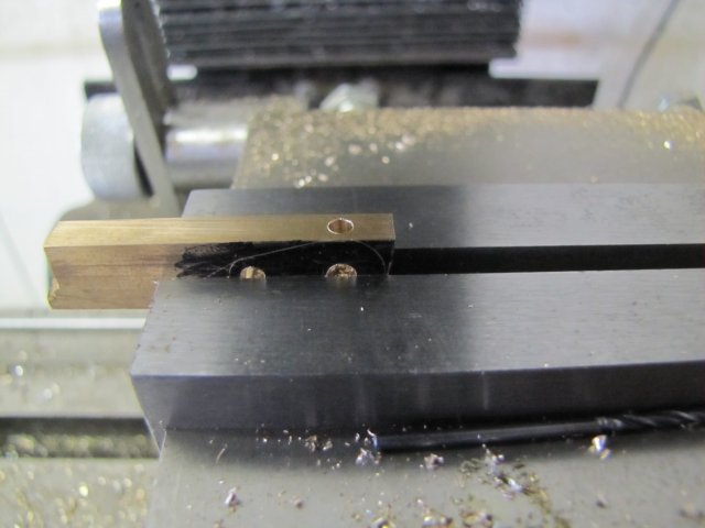
Rounding over with facets before filing:
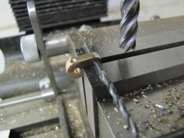
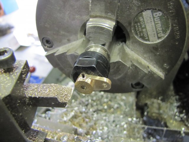
Thinning it down - I used a bit of 3mm rod chucked up in the ER11 collet chuck. Just filed a flat on it for the grub screw to hold onto, and turned it down. You'll see that the grub screw was a bit long, and I'd turned a bit of that away in the process as well:
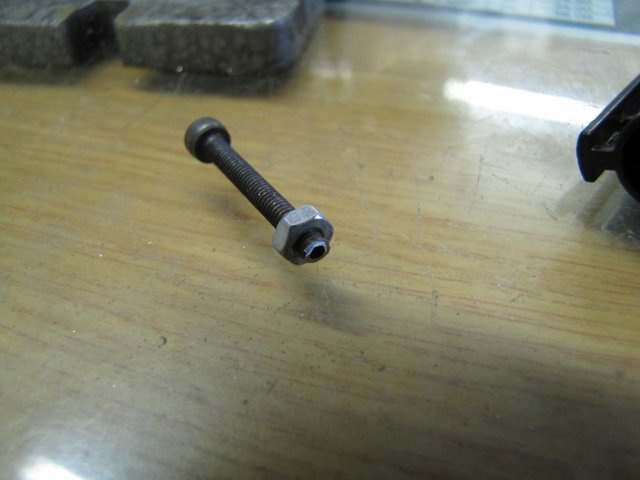
To get more use from that same grub screw , I just screwed it half-way into a 3mm nut, and with a 3mm cap screw turned in from the other end of the nut to lock up against it, I had enough to hold on to to go to the bench grinder and grind off the excess:
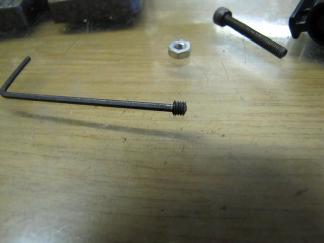
The grub screw was still a bit long, so I plonked it on the end of an Allen key and carefully ground down the other end as well to shorten it further making a slight point on the end:
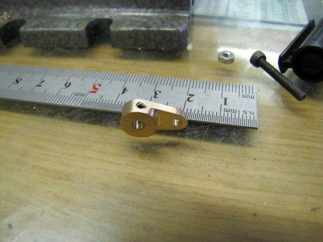
A bit of work with a fine file and emery, and the valve arm is done:
The bits left to make are getting less now, but some things depend on getting the engine assembled partly to take some measurements. I did start to clean up the two bits of brass plate cut in an earlier post - that's the start of the connecting rods:


I guess I'd better start putting drill bits back in the index - before they slip into the fourth dimension.
Before I left shop for the day, I gave the offending column another coat of paint; it still does not look great, but I'll let it dry for a couple of days and give it a rub-down with some 1200 emery before a final coat of paint:


, Arnold