Well you guys told me to get my act together and share some projects. I have two on the go at the moment but. One is a power feed for my Seig SX3 mill based on a 14.4 volt cordless drill motor and the other is adding an Arduino controlled electronic dividing controller for my as yet unused Vertex Rotary table. I think they will be firly slow builds as I still work and getting quality shed time is pretty hard!
But anyway here is part 1 of part 1....
I have some stepper motors in a box of tricks. three of them are NEMA17 and 1 of them is a NEMA 23. I have seen a few people use an Arduino to make a rotary table NC controller and because I have played with these beasts, I thought I would give it a go. So being in Australia, I grabbed one of these
 http://littlebirdelectronics.com/products/arduino-uno-r3
and one of these
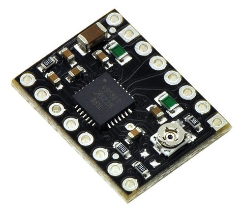
 http://littlebirdelectronics.com/products/a4988-stepper-motor-driver-carrier-black-edition
and I figured I better be able to see what is going on, so I got one of these
 http://littlebirdelectronics.com/products/lcd-keypad-shield-1
and a tiny heatsink
 http://littlebirdelectronics.com/products/small-heatsink
And in exactly the same time it took to get an order from CTC from Hong Kong, it all arrived from Sydney 800 km away. Lucky I paid extra for Express Post

Anyway, I busied myself with configuring the Arduino and remembering how to code in C but by the end of the night, I had got some code written that very roughly used the keyboard. The video thumbnail gives you an idea how big the stepper controller is.
Anyway, not too bad for one night. The next night, I headed for the shed, grabbed my soldering iron and started to put some stuff together

So what have we got?
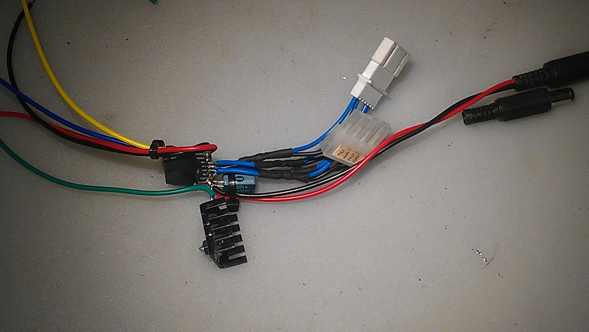
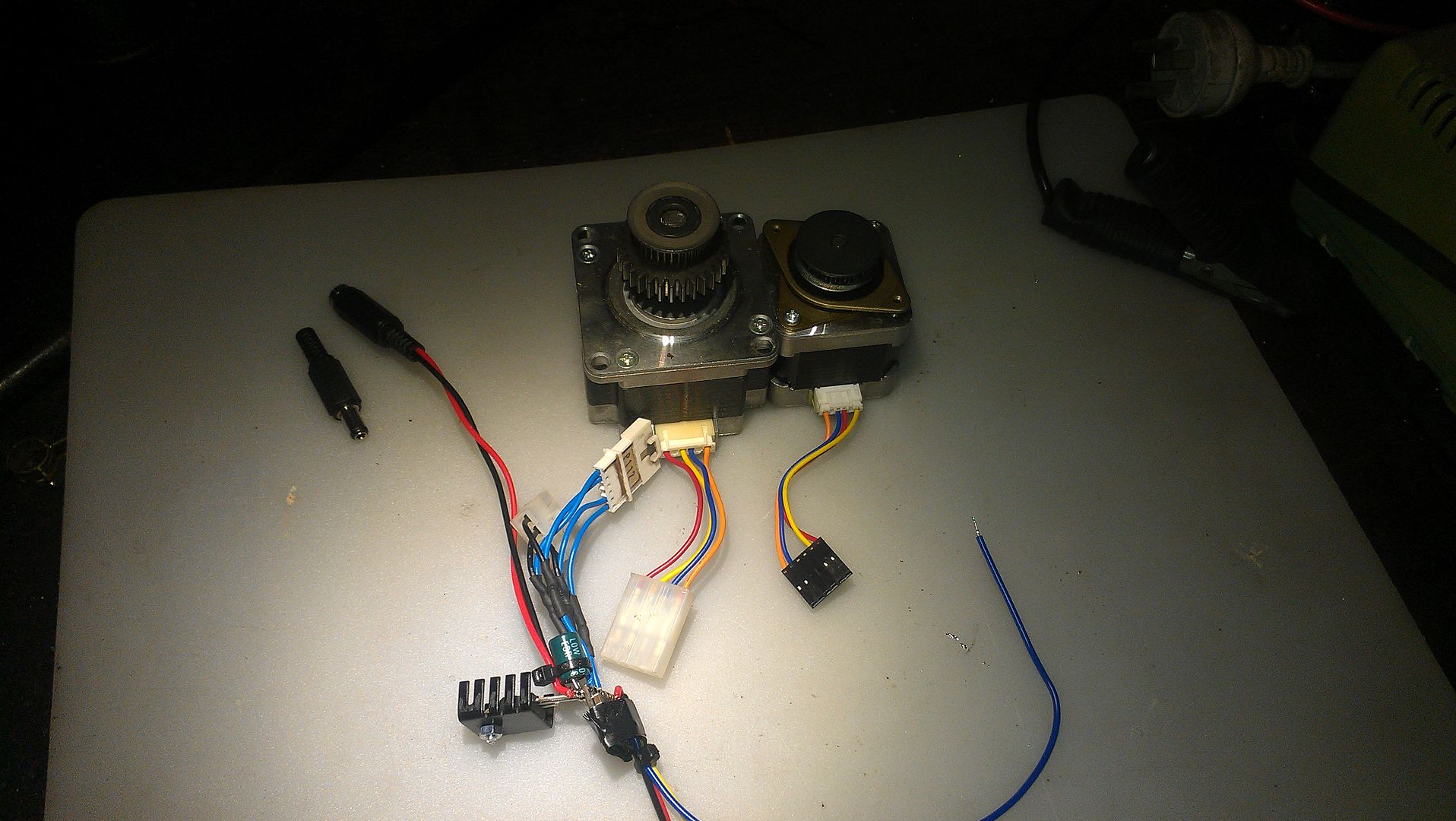
Well I started off soldering on two different sized stepper drive connectors. One for NEMA23 and one for NEMA 17. To the right is an inline power connector to receive 18.5 volts from a laptop power supply once I solder on the loose connector beside it. At the bottom is a 12 volt regulator and heatsink to step the 18.5 volts down to power the Arduino. Above that is the stepper board itself wrapped in insulation tape holding the heatsink on while the heatsink plaster/glue dried. The red and black wires will feed the logic side of the stepper board from the built in 5 volt regulated power on the Arduino. The blue and yellow wires are the step and direction signals and the green wire is 12 volt power for the main Arduino supply.
Here's another pic

So it s night three and time to see if I can get the stepper going. Initially I had trouble and I found a bit of code on the Pololu forum that did the trick but not straight away as it was a bit hit and miss. I wondered if the tinned wires I had stuffed into the Arduino ports were not getting a good connection so back to the shed to solder them onto a header strip and this time, it worked perfectly!
So now if you are hooked on this project, here are a few more short videos (all of these are taken with my phone). I tried to merge them together but it took ages. There is only 7 minutes video in total so enjoy
This one shows an overview of the bits
This one talks about the keyboard.
SO I had a bit of a play with this all for the evening and concluded the NEMA 17 was a better match with the controller but that I was really asking too much of the postage sized stepper controller and was thinking I might get a Gecko GX251X controller.
http://www.geckodrive.com/geckodrive-step-motor-drives/g251x.htmlUnfortunately, I don't have any specs on these steppers. I think they must be custom made by Minebea. I think the bigger one is 3.3 amps and the smaller ones must be around 1 to 1.4 amps based on specs of available products from the manufacturer.
Anyway, I will just focus on developing the software in the evenings now I know I have a goer and finish off as few part finished jobs.
For the programmers, here is the short sketch I found that is driving stuff in the second video.
#define stepPin 4
#define dirPin 5
int dir = HIGH;

void setup() {
  Serial.begin(9600);
  Serial.println("Starting stepper exerciser.");

  pinMode(stepPin, OUTPUT);
  pinMode(dirPin, OUTPUT);

  digitalWrite(dirPin, HIGH);
  digitalWrite(stepPin, LOW);
}

void loop() {
  int i, j;

//  for (i=2000; i>=400; i-=200) {
//    Serial.print("Speed: ");
//    Serial.println(i);

    i = 400;    // maximum speed it can do
    for (j=0; j<1000; j++) {
      digitalWrite(stepPin, HIGH);
      delayMicroseconds(i);
      digitalWrite(stepPin, LOW);
      delayMicroseconds(i);
    }

    delay(500);
    digitalWrite(dirPin, !digitalRead(dirPin));

    for (j=0; j<2000; j++) {
      digitalWrite(stepPin, HIGH);
      delayMicroseconds(i);
      digitalWrite(stepPin, LOW);
      delayMicroseconds(i);
    }

    delay(1000);
    Serial.println("Switching directions.");
    if(dir == HIGH)
      dir = LOW;
    else
      dir = HIGH;
    digitalWrite(dirPin, dir);
//  }
}
Pretty simple Huh!
So here's where I can use some help so feel free to chip in to answer some questions.
1. Which sized stepper should I use on a Vertex Rotary Table? NEMA 17 or NEMA 23?
2. What features should a stand alone Rotary Table controller support?
3. Which "Real" stepper driver should I get?
4. Can you live with a slow build?