Hi everyone,
When I was turning the ER25 chuck and the hand wheel from large diameter steel I realized I would need to add more reduction to the lathe drive train to get better torque.
The design and build is being done as I am proceeding and adapted to materials on hand.
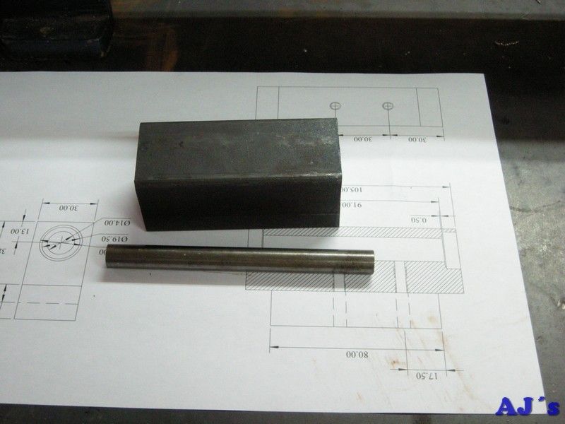
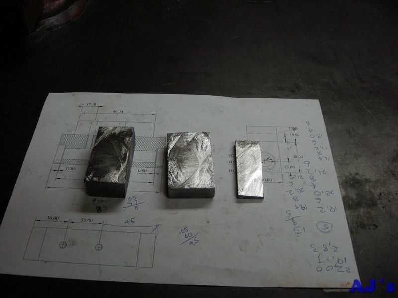
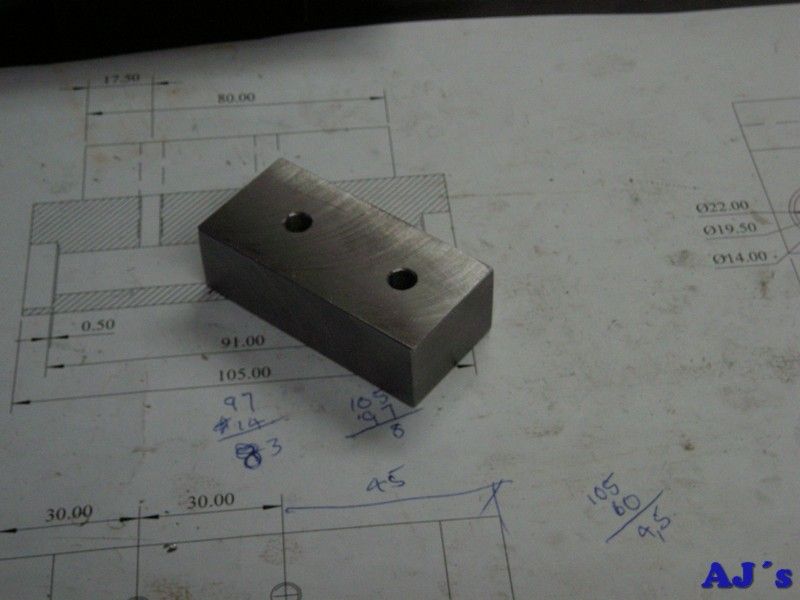
Started with a piece of 40mm square HRS and some round bar.
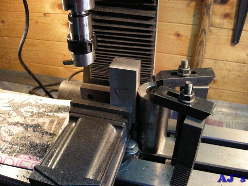
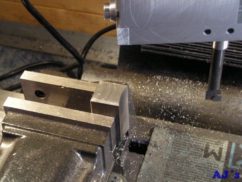
The square bar was squared up and cut to size on the mill.
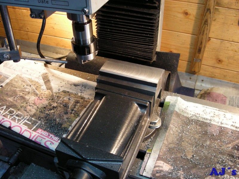

Setup square on end and finished with a fly cutter
.
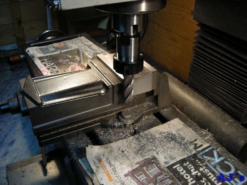
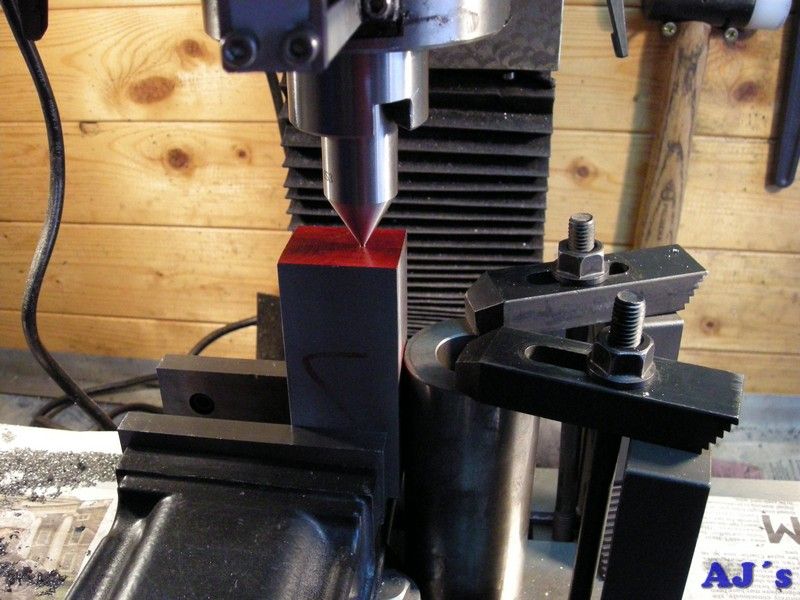
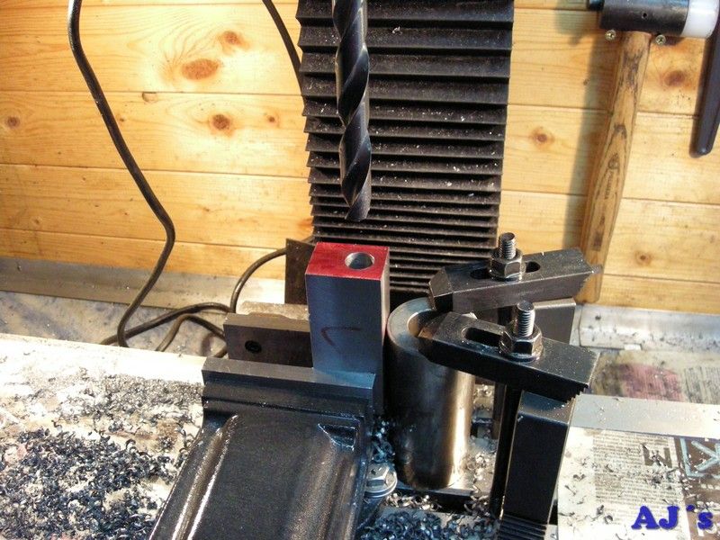
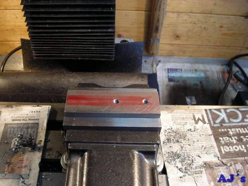
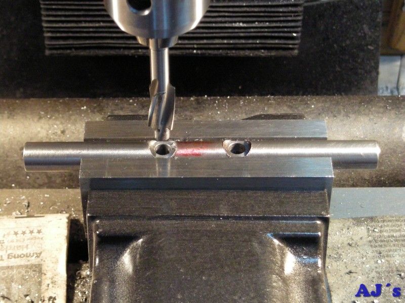
The shaft hole was marked out, located and drilled through.
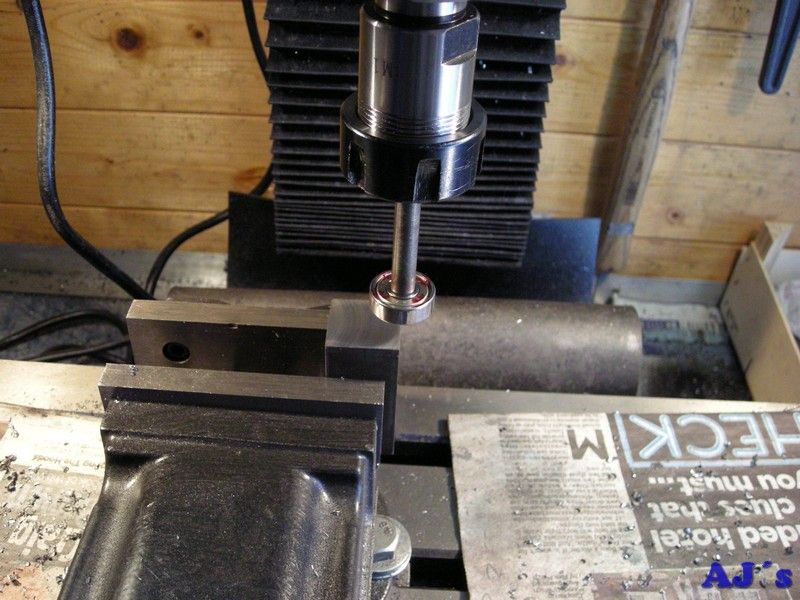
A bearing seat was bored.
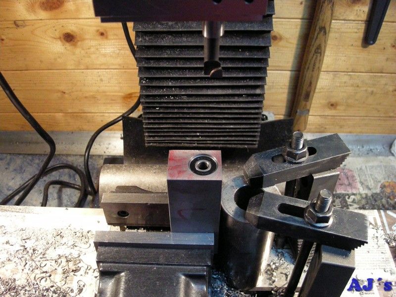
Then it was flipped over and the other bearing seat bored.

Mounting holes was drilled and tapped to coincide with the original motor in the lathe.
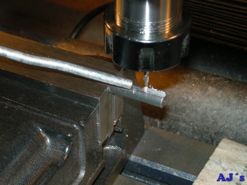
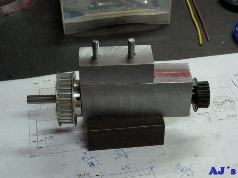
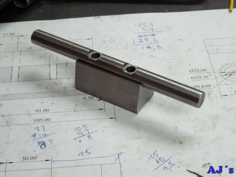
Next, keyways was machined in the ends of a piece of 8mm round bar to form the shaft.
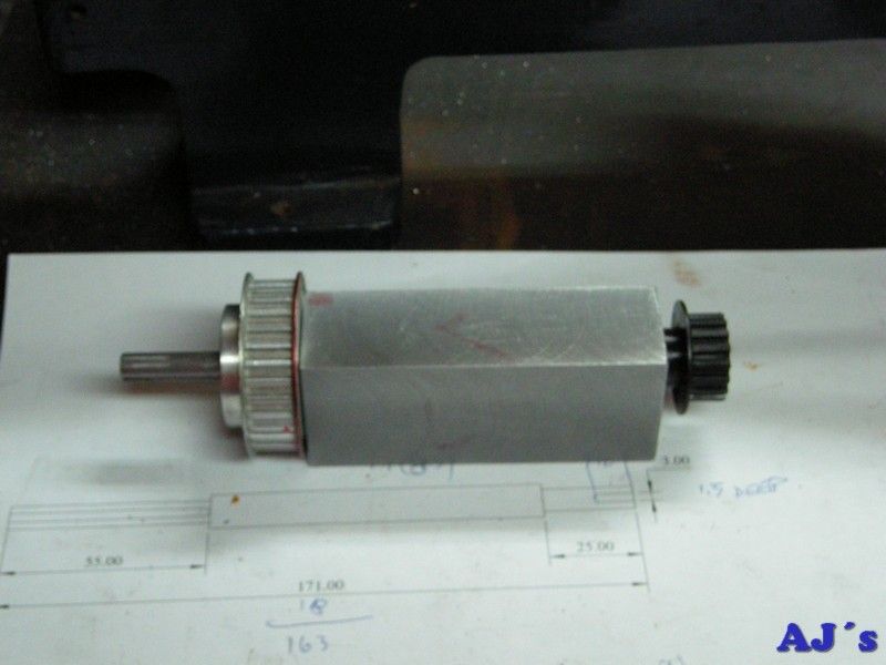
The shaft support finished.
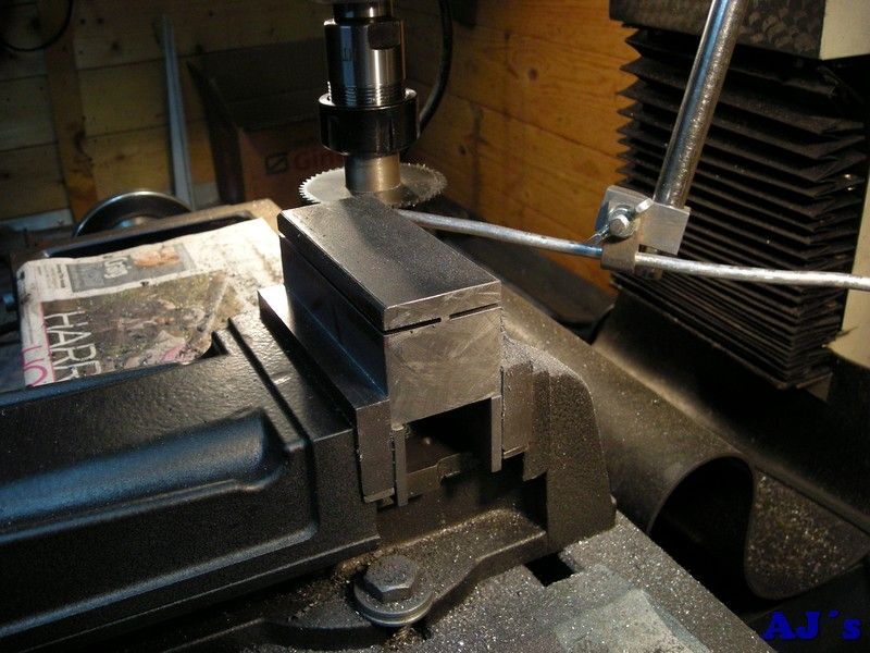
Another chunk of square bar was sawn and machined to form a spacer for the support.
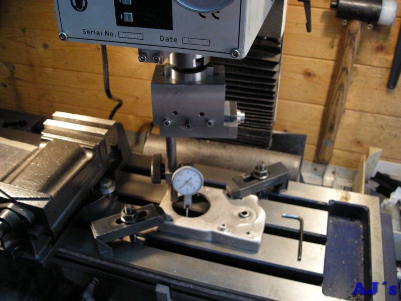
For the new motor mounting a piece of 25mm calibrated square bar was setup and edges located on the mill.

And the motor radius was machined on one side using the boring head.
Forgot to take photos of the rest of the bracket's procedure.
Drilling and spot facing holes in a piece of 12mm shaft.
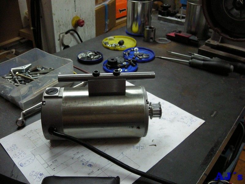
And together they form the motor mounting.
Drilling and reaming some holes in the fixing clamps.

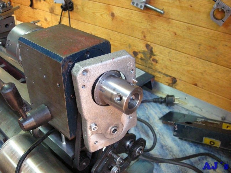
All mounted on the lathe.
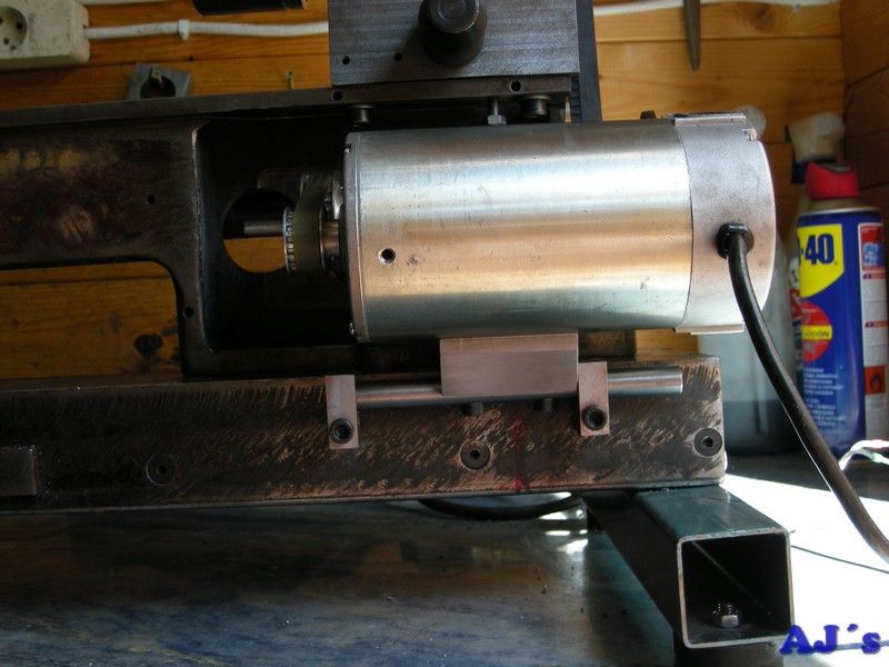
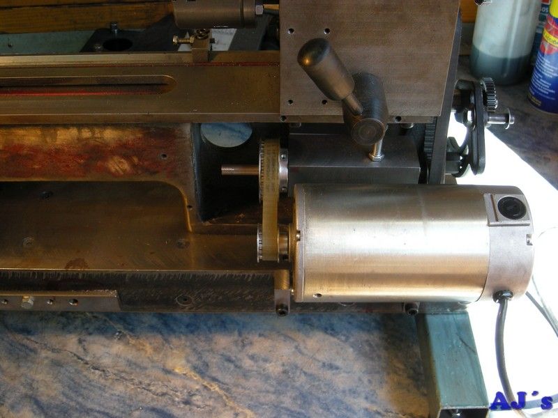
As part of the reassembly process, the hole in the aluminium cover for the belt drive was bored bigger so it can fit over the tachometer disc on the spindle.
Now waiting for belt and pulleys to arrive. There will be three different pulleys on the lay shaft and the motor can slide in the clamps to align with any of them. Will start wit 2:1, 1.5:1 and direct ratios and see how it works.
Next, as part of this mod I will also add extra support to the rear of the headstock.
Cheers for now.
Abraham


