A few weeks ago, I replaced the motor on my lathe with a Leeson 220v and a Teco VFD. The belt changing was getting old and now I have variable speed and plenty (for me) of low end torque.
The last stage of this was to add a tachometer.
I was going to get the Machtach, but it's been in a kind of limbo while the new owner figures out how the biz should be run.
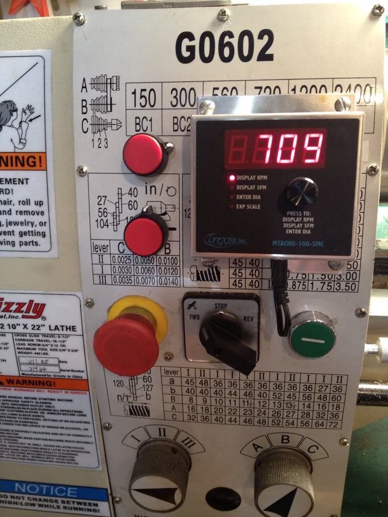
I ended up with the Tachulator (who names these things?) which displays not only RPM, but also SFM (after diameter input.)
Easy install. A few pix here on my Grizzly G0602.
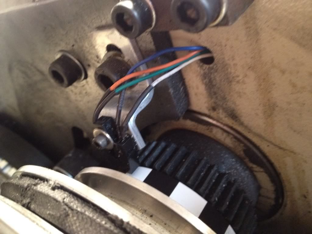
Sensor mount
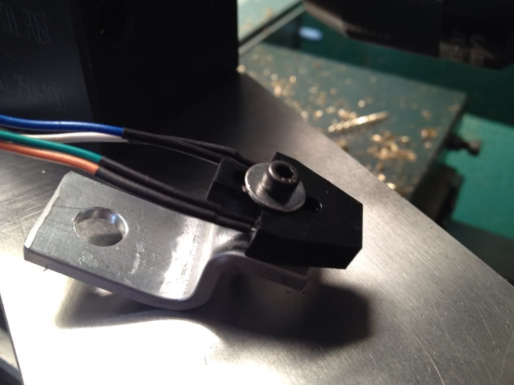
The sensor mounted with a 16 segment timing strip on the pulley. You can actually use any number of segments from 1 to 16. The low end accuracy increases with the number of segments. 16 is the max and, according to the specs, is accurate to 3 rpm. The very strange thing was the first timing strips I made were printed on a pigment ink, inkjet printer. (Epson 9800). The IR sensor refused to recognize the difference between black and white. The instructions mention this issue with some laser printers and suggest switching to a laser printed sensor strip. I did so and it works perfectly. Go figure. Must be an issue with reflectivity of pigment inks. Inexpensive ink jets that use dye inks apparently don't have this issue.
FInished with the control box mounted on the lathe. The two knobs to the left (labeling is coming) are the speed pot for the Teco FM50 VFD and, below it, the speed control for the carriage feed.
Happy to answer any questions.
Best,
Stan


