Cheers John

- the camera is slowly turning "shinier" with time

.
Rob, Cheers mate
Thanks Pete
- I worked mostly off Dean Williams's design - and Steve Campbell drew up the plans for that; you can download the plans from
Dean's site here.. Some bit's like the threaded split-collar collar to adjust the bearing tension I just did on the go, so there are no drawings for that; I'll dig through my paperwork later today to see if I made any scetches (C-o-Cs) back then. Attached are some crude pdf's of CAD drawings I did for the eccentric and zero-able handle back when I built the RT. There are no measurements on them; like I said, I did things off the cuff. The zip file contains dxf CAD drawings for both.
Thank you dgralying
- Welcome to MadModder

. Don hit it spot on - I've only been machining for about 3 1/2 years, and just jumped in and tried while learning from others. It's not for me to rate my level of craftsmanship; I have always and still do just try my best at any bit of machining I attempt, be it the simplest task like making a toolmaker's clamp or a more complex job like building this rotary table. Sometimes it can be hard work and one wonders if it's worth it; that's the point when I just grit my teeth and dig deeper - some people run marathons, others climb mountains; for me it's making tools and model engines. I've on purpose shown throughout this build there are mistakes and booboos; those will happen. Anybody can do what I do; I'm really not special. Just jump right in and give it your best shot
30 May 2010Well, not much to report for the day; I spent most of the day getting to my mill's spindle (I finally could after getting circlip pliers!), disassembling it, cleaning everything thoroughly, and re-assembling and adjusting the bearing pre-tension. No photos of the process though; my hands were too dirty to use the camera

.
And boy-oh-boy, what have I been missing out on! Once adjusted and re-assembled, I played around with bits of scrap to see how much of a difference the cleaning and adjustments made, and I was totally surprised! MUCH better cuts, and MUCH improved finishes, even when cranking at a good clip. A difference between night and day.
One of the scraps of HRS I practiced on became the two locking clamps for the RT. After testing the flycutter on some scrap I decided it was worthwhile to jump in and fully flatten and square up the side on which the RT will be used in the vertical position. Standing on edge it was close to, but not fully square, and I ended up using a 0.05mm feeler gauge plate to shim it to clamp it down nice and square. More "no photos", but I took a short video clip while starting a flycut on the surface. If you are prone to seasickness, please do take some Dramamine or ginger first; I was holding the camera in my right hand and cranking the table with my left hand:
Then I drilled and tapped the top of the base M6 to mount the locking clamps - here is a view of the flycut face and one of the clamps mounted; the other one is on the opposite corner of the table:

So, not much to show, but a whole lot gained, for the day's bit so I'm confident that I can now start on the T slots in the table for the next step.
02 June 2010I decided to make the thumb screw to operate/retain the eccentric. Originally I was going to make it from some scrap HRS bar, but I decided to make it match the handwheel assembly, and opted for an aluminium unit, with a length of 5mm threaded rod screwed and loctited in:

The thumb screw went so quickly that I wasn't satisfied... I had an itch and it needed scratching.
So I decided to start setting up the table for machining the T slots. I've thought through and visualized the machining steps for cutting these slots over and over in my head, and nothing seemed out of whack. First I placed the rotary table roughly in the spot I wanted it for machining, and cranked the mill to roughly center it below the spindle. I took careful note of the direction I was moving the handwheels and zero'd those. Then I cleaned the mill table thoroughly, put a piece of paper below the RT, and with a bit of 16mm silver steel (to match the deep hole in the RT center) gripped in the mill's collet chuck , I lowered the quill to center the RT and locked the quill:

With the RT held on center from the mill spindle, I then used an engineer's square against the side of the RT base I flycut in a previous post to get the RT base square to the mill table - flipping the square over while checking, as well as checking from both edges of the mill table. This is not a very precise method - it would have been better to use a DTI to test, but I felt this was one of those jobs where "good enough" is, well, good enough. T-nuts are not all that precise... , especially if I made them!
Then I clamped the RT base down solidly on all sides, set the RT and it's handwheel to zero degrees, locked the RT table with it's own clamps, and as an added safety precaution, added an additional clamp on top of the table. I don't want anything to budge. I also scribbled down all the necessary readings, directions of feed, and a couple of things to check regularly while machining on a bit of paper:

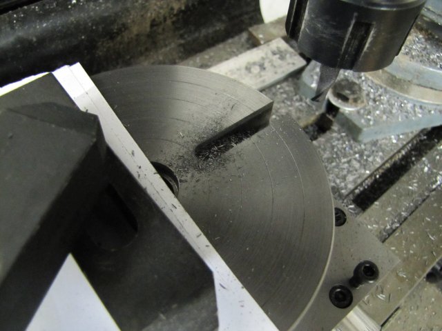
Maybe I should have stopped there, but the temptation was too big. I decided to go for the first cut... a new 8 mm slot mill, mill set to it's lowest high speed range, 2.5mm depth of cut, and at the start something felt wrong; way too much vibration, and the milling bit wasn't really cutting well... Normally I slow down when this happens, but I had a "gut feeling" that in this instance I was going too slow... I've started to trust that "gut feeling". So, next speed up, I started feeding slowly, and things went much better. Then I started cranking the handle a bit more quickly, and everything came together; I had nicely shaped chips coming off and no heat that I could detect

The first pass done and with a nice finish as well:

After 3 more passes at 2.5mm DOC and a last pass at 1.8mm DOC, I was down to depth
:
The swarf magnets and my tummy was insisting at that point to have dinner, so I stopped there, with the needed settings added to my list of notes.
03 June 2010I rushed home from work this afternoon! And finished milling out the centers of the T-slots - without rushing. I followed the check list I made and the readings I jotted down to the last drop - including checking between each slot that nothing had come loose from vibration anywhere. On cutting the third slot, I had a bit of a scare; at one point the milling sounds started sounding different from the previous slots - and the feel on the handwheel was "less positive" for lack of a more "tactile" description - so I punched the emergency stop, and checked everything through again. I found that the drawbar had worked slightly loose. I try not to over tighten the drawbar on my mill's MT4 spindle; well, I'd under-tightened it, and the collet chuck had come loose in the spindle... Fortunately I caught the problem in time, and just re-tightened the drawbar; I could not even see any abnormality to the slot caused by the chuck coming loose, so I carried on. The result:

Finishing the three slots left after yesterday's one took me less than 45 minutes to do, and I was feeling both alert and relaxed at that point, so I decided to push on. I changed to the T-slot cutter. To find zero on the Z axis after changing the cutter, I unlocked the feed wheel, and used the drilling arms to lightly pull down the quill to the point where the cutter touched a piece of paper on the RT. Then, without locking the Z feed wheel, I cranked it to zero (in down-feed direction to compensate for some backlash) and then locked it on, and used it to reverse the quill. My mill's Z feed is not zero-able otherwise... I guess I'll be making another zero-able handwheel in future!:

My T-slot cutter's diameter is too small for my exact requirements, and it also cuts a slightly too high undercut for the slots. I wanted the slots on the RT to match my Myford's slots, and I had to have a compromise. Well, if I made the cutter myself that would not have been necessary, but with the bought one it was. With the smaller cutter diameter, I had to offset the cuts to get enough undercut on both sides, rather than finishing in one pass.
For one pass, things were A-OK; I could feed in on the Y axis and do the pass with a nice conventional cut. The opposite side was a problem; I would be climb-milling. I dug in with the first cut, and to try to get a conventional cut on the return on the opposite side, I tried back-feeding on Y while at the deep end of the cut on X. Things just did not feel right, and the cutter was "complaining"... So I reversed the Y back-feed, brought the cutter out on X and tried the climb cut with two passes on Y. It worked with a slow and steady feed
- and I finished the first T-Slot:

The other three T-slots were formalities, except the last one... I had to keep telling myself to "Keep it steady; don't rush; pay attention" on the last cut; it seemed to take forever but was at the same speed as the others!
Everything came out well though, and this is the result:


For those who swallowed the obligatory Dramamine or ate a bit of ginger:
[ Invalid YouTube link ]
The RT is now pretty much operational; I will still finish it with a bit of lapping like Dean demonstrated in his build, as well as add a couple of other "touches". In fact, I'm pretty pleased with the outcome up to now, and with not much left to go wrong, I broke out the VSOB and had a good glass of Chivas on the rocks to celebrate
- My apologies if this post was a bit "under the influence"

The "chuck adapter" for the RT to take my lathe chucks will still be quite a bit of work though!
, Arnold


