[Moved from homemodelenginemachinist.com]
I worked on the valve chest today, which seemed to be a bit slow going.
First step after marking up: square up the inside a bit. No critical dimensions here, just need room for the valve to move.

This kit is old enough that the valve guide is cast into the valve chest; the newer models have a brass fitting that you machine separately, then screw in. I suppose that avoids having to drill deep through the valve chest and adds some brass bling, but I think I prefer the old way.
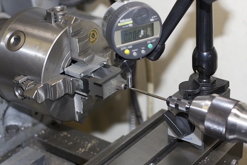
Anyhoo, the valve chest was chucked up in the 4-jaw with some backing, and a wiggler and indicator used to center on the punch mark at the end of the valve guide:
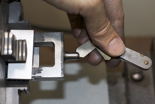
I started with an HSS ground tool bit because of the interrupted cut, and to take the crust off the casting. Towards the end I switched to a carbide insert tool, which does risk getting chipped because of the interrupted cut, but actually performed fine. After a bit of turning we're close. Both radii were done "freehand" and cleaned up with files. Here I'm using a radius gauge to check the shaping on the end:
and in this photo the neck radius still needs some cleanup. With a bit more work it's almost done:
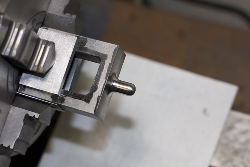
but I still need to get rid of some tool marks around the base.
Now it's time to drill and ream for the valve rod. The angle plate on its side serves as a useful way to hold the casting square (the sides have already been machined), and we locate on the punch mark:
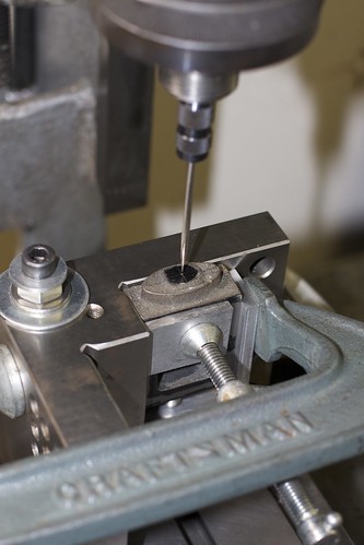
The top end is drilled then reamed 3/16", and the bottom end has a 1/8" hole reamed into the valve guide. Luckily, for the lower hole, I had an extra long drill that I'd picked up at a yard sale or flea market a while back, but of course it wandered all over the place when trying to enter the bottom of the casting.
My solution was to clamp a block of Al inside the valve check, switch back to the stubby drill then drill through that to form a guide for the longer drill.
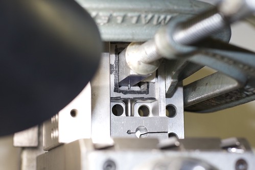
This worked nicely; with the block still clamped, it acted as a guide for the longer drill which no longer wandered, and I was able to complete the lower hole, then ream 1/8".
The upper hole was also opened up to 3/8" using a small boring tool; the valve rod gland fits into this.
I now pondered long and hard about how to do the profiling on the lower side of the valve chest. I guesstimated from the plans that the curves have a radius of 1", then blend into a radius around the bolt holes. To machine the curves, my options were the rotary table (setup too hard on my tiny table), the faceplate (easier setup, but hard to control the radius from the center), and the 4-jaw. After hatching a cunning plan to get the right offsets, the 4-jaw won.
I used a scrap block of Al as a simple fixture, and computed and marked out two punch marks:
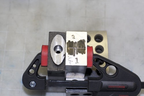
When the fixture is located in the 4-jaw with the appropriate punch mark centered, I know that if the valve chest is clamped against the fixture the right way around, I'll hit that 1" radius for that side of the valve chest.
Here's the 4-jaw setup, with the fixture clamped in the middle, and the casting held by just one jaw.
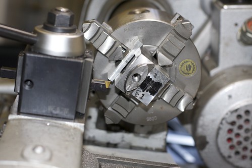
Not an ideal way to hold something in the 4-jaw, but the setup was pretty rigid so I wasn't too worried. I've already centered the fixture on punch mark no. 1, then I had to fiddle around a bit to get the casting lined up (using a square to align the chuck, and a height gauge locating on a drill bit which was a tight fit into the reamed hole). I've mostly finished one side in this photo.
After doing both sides it looks like an eye

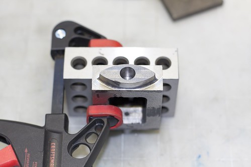
I didn't quite get things lined up, so there's a bit of a step where the machining of the two sides comes together; I'll have to clean that up by filing later.
Back onto the mill, using the angle plate setup again, to locate, drill and tap the holes for the gland screws:
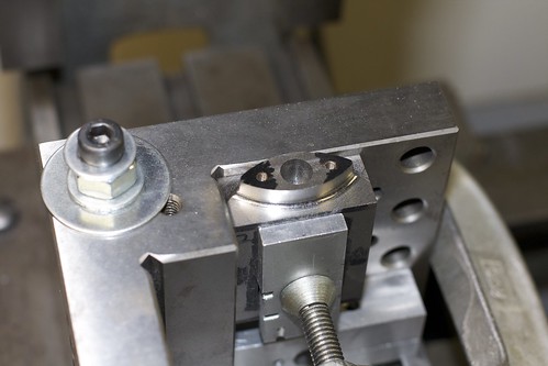
Now another crazy setup ;D I wanted to round off the corners of the "eye" shape on the rotary table. The only way I could figure out how to hold it was on the angle plate:
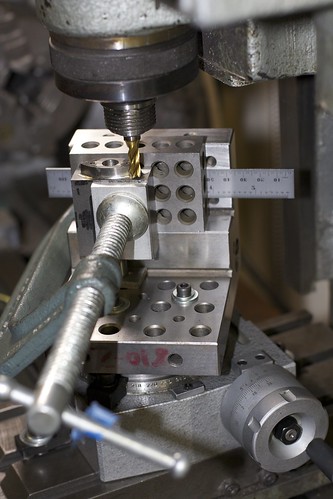
There's a little rotary table under there somewhere! Usual rotab drill: locate the rotary table under the mill and clamp it down. Set up the part on the table, also centered (I used a drill bit dropping into one of those tapped holes for location). Now use the carriage to adjust the radius being cut.
I don't have any ball-end mills of the right radius, so I milled a few steps, then cleaned up with a file. Here we are, one side done:
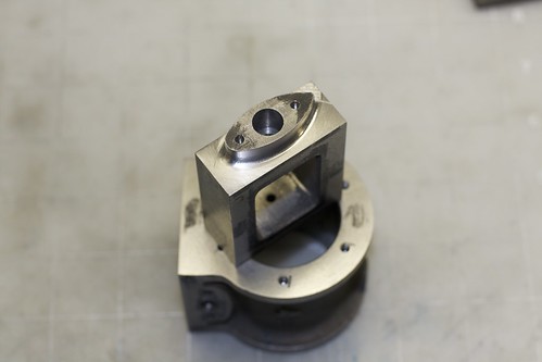
This part is on the underside of the valve chest, so I don't have to get too crazy with finishing, and it might even be painted. I can never decide whether to paint valve chests!
Tomorrow I hope to finish the profiling here, mill the chest down to thickness, do the valve chest cover, and drill and tap for the studs that hold the valve chest to the cylinder.