Author Topic: Adding coolant to the mill  (Read 7204 times)

Offline mzt

  • Jr. Member
  • **
  • Posts: 88
  • Country: it
Adding coolant to the mill
« on: April 26, 2012, 10:13:36 AM »
Got a salvaged pump taken from a scrapped industrial drill press: they told me it’s three phase, but it can also be wired to single phase. I don’t know how, yet.
First of all (that’s even before knowing whether the pump is working or not) I made the sump out of an old plastic tank, a plastic IKEA chopping board and lots of sillicon glue.
Turning that chopping board into the lathe was fun: once in a while the machine didn’t complain about the depth of cuts. (Them chips were a pain to clean, tho).
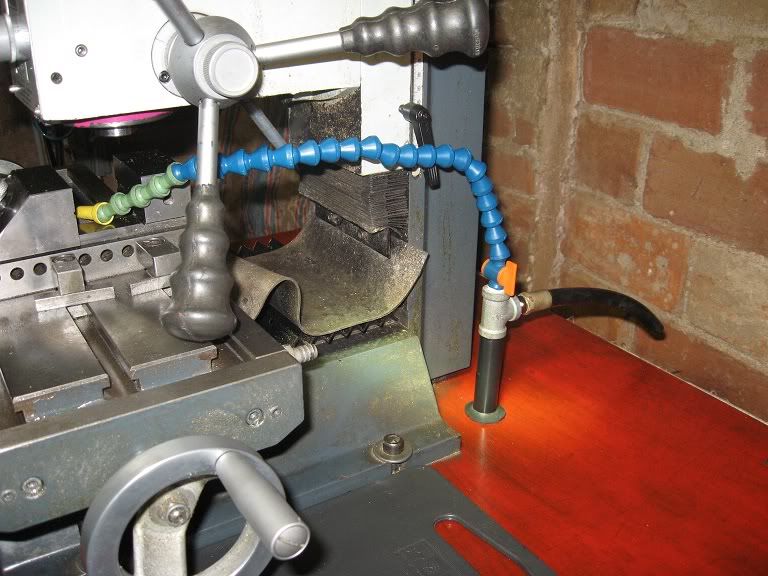


Here’s the pump.


A quick glance into the “plumbing stuff” box revealed some usable items: a second valve is missing, together with some small fittings,
but the problem will be easily solved next time I will get close to an hardware store during opening hours.


The two plastic strips with holes and screws in the above photo should act as a (temporary, You bet) pipe securing clamp:
I will put it upside down under the bench top, tighten the clamping screws over the pipe and then screw in the other two
(maybe four) screws against the ‘roof’ to hold it steady. A 14mm nut will  do a better job, the day I will find an M14 die.
Threading that short pipe into the lathe could be an option, too.

The idea being to have the coolant feed line split into one line going to the work area and a second line (that short black rubber pipe) going back to the sump
for flood regulating purposes. Of course that second line might be used to feed coolant to the lathe, the day I will get around to it.


The hardest part of the job was hand drilling a 13mm hole into the bench top for the pipe to pass through: had to deal with a wobbly gun drill and a blunt bit.

You might appreciate a picture of the mill and her dentist’s lamp, sitting on the self made workbench


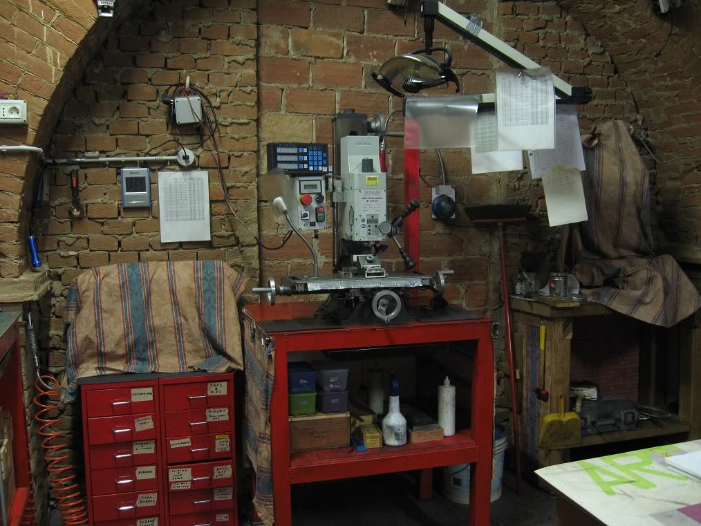
(Please, do not ask for close pictures of the :bugeye: welds).    :lol: :lol:
 

Marcello


Offline Jonny

  • Hero Member
  • *****
  • Posts: 780
Re: Adding coolant to the mill
« Reply #1 on: April 26, 2012, 05:17:11 PM »
That 3ph pumps no good to you, send it me mines packed up on the lathe 160mm depth.

On both mills i have the Locline off the quill, no need to constantly keep repositioning either with X, Y or Z.
Did try a mister well better than those a Noga mister, prefer proper coolant.

Offline Jonny

  • Hero Member
  • *****
  • Posts: 780
Re: Adding coolant to the mill
« Reply #2 on: April 27, 2012, 04:35:25 PM »
Just a thought, i would enlarge massively the outlets.
Reason being they will constantly block up the screw in adaptor and pipe out of it = pain.


Offline mzt

  • Jr. Member
  • **
  • Posts: 88
  • Country: it
Re: Adding coolant to the mill
« Reply #3 on: May 02, 2012, 04:10:21 AM »
Jonny,

You're probably right about the 3ph pump: a friend electrician told me there's probably no way I can wire it for single phase, but will study the problem.  -  :coffee:

I have ideas I could replace the pump motor with one taken from an electric fan: I'd get a 3 speed pump, too!

I could find no place for the locline in the quill without having it constantly in the way when operating the mill or changing tools: went for the mill stand mounting with the intent of having it definitely out of the way when it is not in use (and that will be most of the time, I suppose.) That way, I will have to reposition Z only. Someday, I will go for a stand mounted chip protection shield, too (that table mounted one is a pain to use).

As for the chips clogging the outlet (there's only one) : that will be a problem I will have to face.

Thank You
Marcello

Offline Lew_Merrick_PE

  • Hero Member
  • *****
  • Posts: 690
  • Country: us
Re: Adding coolant to the mill
« Reply #4 on: May 03, 2012, 11:46:22 AM »
Marcello -- Depending on a number of things, a solution to chip clogging for me has been to form screen-door type screen into either: (1) a "top-hat" shape, (2) cone shape, or (3) long closed-end tube shape (i.e. thin, long "top hat") that fits into the drain port, but can easily be removed for more intensive clean-up of swarf.

As to the motor issue, I have built several pump systems over the years using motors scavenged from washing machines & dryers.  I don't think I ever paid more than $5 for them (but this was a couple of decades ago the last time I did this) and many times got them for free.  The "trick" is that, since these motors will NOT be splatter or drip proof, to enclose them in a shield (allowing for good cooling air flow) and run power through a flexible shaft type of drive.  I even made one using (steel reinforced) hydraulic hose (needing some "guides" to support it) that worked quite well (I filled the hose with marbles to keep it from collapsing).  I more commonly used the cheap "90° drill adapters" that used to be sold in the "cheap tools bin" at my local hardware stores.

Offline mzt

  • Jr. Member
  • **
  • Posts: 88
  • Country: it
Re: Adding coolant to the mill
« Reply #5 on: May 04, 2012, 02:34:49 AM »
Lew,

now You tell me that, I recall there were some sturdy motors scattered in the backyard. They might even be DC or lo-voltage AC, and that would be safer too. 
A couple of gears or a belt drive would do, eventually, should I need to increase or reduce the speed.

In the meanwhile, I added the second valve and replaced the short steel pipe with a longer M16 bolt, which I turned down to 14mm except for the M16 threaded part, drilled through 8mm and tapped 1/4" water pipe were the hex head was. Now, I have the means of fixing it securely to the mill stand through a couple of nuts.

This quick 'n easy mill coolant is slowly drifting towards a major project. Will end with a coolant tank hanging from the ceiling and a second one below the stand...

Marcello

Offline Lew_Merrick_PE

  • Hero Member
  • *****
  • Posts: 690
  • Country: us
Re: Adding coolant to the mill
« Reply #6 on: May 04, 2012, 12:03:12 PM »
Marcello,

It sounds to me as if you are suffering from expanded project definition syndrome.  As a mechanical design & development engineer, I see this all the time.  The solution is to create a project definition document.  Understand that such things are (and always will be) a work in progress.  That is the nature of the biz.

How much flow do you need at the point of application?  How high above the lowest level of the sump will you have to raise your coolant?  These two questions size your pump (adding, of course, a Murphy Phactor to compensate for the differences between theory and reality).

What do you have available, can get cheap, or can make that fits that bill?  Laying out these options will clarify things for you.

One pump I built (circa 1975) was a piece of PVC 1-1/2 IPS pipe with a piston in it making it a double-acting cylinder pump.  Two check-valves on each action side of the piston gave it nice flow.  A low-speed DC motor scavenged off a broken winch gave me speed control using a variable voltage power supply having the motor drive an eccentric to stroke the pump.  Placing an expansion chamber made from PVC 6 IPS pipe reduced the "pulsing" from the piston pump to an acceptable level (though it added a minute or so of wind up at start-up).  The whole thing attached to a 5 gallon plastic paint bucket.

As I have rather significant air compressor flow available, I have built several Bernoulli-type suction pump systems.  I have built a couple of systems based on (scavenged) aquarium pumps -- some worked well, others had compatibility issues with the coolant.  I even built one (back in the 60's) based on an automotive water pump out of a scrap yard.

Once you have your components selected, some actual design time will save you hours of frustration in the shop, right?

Offline mzt

  • Jr. Member
  • **
  • Posts: 88
  • Country: it
Re: Adding coolant to the mill
« Reply #7 on: May 09, 2012, 03:39:01 AM »
RIGHT!

Still... I have not the faintest idea regarding my needs about coolants.

I'm machining dry most of the time, occasionally squirting a drop of petroil from a bottle, or clearing the chips from the mill with the aid of a brush. A toothbrush loaded with oil, held in the groove while parting steel on the lathe (Loda smelly smokes, tho: I don't like that).

Told a friend about that, answer was: "get that pump and put it into use, You'll see what a difference it makes".

Still looking forward...   

(...especially for the electrician to come up with a wiring solution, or no solution at all).

In the meanwhile, I'm making the required fittings, whatever pump (or gravity feed) I will end to.

Marcello

Offline mzt

  • Jr. Member
  • **
  • Posts: 88
  • Country: it
Re: Adding coolant to the mill
« Reply #8 on: May 09, 2012, 05:14:47 AM »

That plastic bracket I’ve shown before concerned me. Decided to go for a sturdier option.

Took long 16mm bolt, turned it down to 14mm and threaded to 1/4”  on one end, leaving the M16 portion as it was. Then drilled it lengthwise 8mm.


That second steel rod comes from the scrap box: it’s already drilled through, but the drill had wandered heavily.
It is on its second salvaging, the first one having been a loosely fitting spindle for an hand tapper I made years ago.

Dieing M10x1: I never got around making a TS die holder for the ‘large’ dies. Only recall about that project when I would need it already made.
(Note: the F/R switch is in the Off position)


Tapping the M10x1 the M16 end of the fitting: that TS tapping chuck came for bucks, but You get what You pay for.
You can see how it holds the taps. It’s not completely unusable, providing You do not hold them firmly and let them float several degrees. 
Someday I will replace its jaws.


When I will have the hole on the mill stand enlarged to 16mm, this will give a sturdy mounting. Hopefully, leakproof.


Marcello

Offline Jonny

  • Hero Member
  • *****
  • Posts: 780
Re: Adding coolant to the mill
« Reply #9 on: May 09, 2012, 03:37:20 PM »
See what will be a future problem and will p you off.
Considering you are using a small bore 8mm, it will block up in minutes.

Lathe i have 1" bore and that blocks up after around 40hrs use.
Other mill i have 13mm bore minimum that blocks up quickly.

As above make sure you put some sort of filter over the outlet from mill table. ie so swarf cant get in to the pipe. Has to be best way to go as piping can be smaller and in turn more flexable.

Offline mzt

  • Jr. Member
  • **
  • Posts: 88
  • Country: it
Re: Adding coolant to the mill
« Reply #10 on: May 10, 2012, 03:08:38 AM »
that 8mm bore would be the feed pipe, hope I won't have so many debris coming from the sump.

The pump does not go to the bottom of the sump, so eventual debrises in that area should not get in circulation again.

The outlet from my mill table will be a problem, the usable bore being somewhere around 6mm.
I'm thinking about an U shaped fence made of thin metal net, fitted to the table, covering an area as large as possible to protect the bore.

Might add a second filter along the outtake pipe, if need arises.

Marcello


Offline grayone

  • Jr. Member
  • **
  • Posts: 38
  • Country: 00
Re: Adding coolant to the mill
« Reply #11 on: May 10, 2012, 06:57:32 AM »
RIGHT!
Still looking forward...   

(...especially for the electrician to come up with a wiring solution, or no solution at all).

Marcello

The only way to convert from single to 3 phase is via an inverter :zap:.  They are comonly available for small machines and generally in conjunction with speed control.  However I think the cost of an inverter is probably more expensive that buying a single phase pump and complete coolant system as these can be had for less than 100 quid :wack:.

Graham
Growing old is mandatory, growing up is optional

Offline mzt

  • Jr. Member
  • **
  • Posts: 88
  • Country: it
Re: Adding coolant to the mill
« Reply #12 on: May 10, 2012, 07:49:02 AM »
He told me yesterday a carefully calculated  :smart: capacitor :zap: can do the job in most cases, but most probably not with that pump I have. Something related to the number of wires in that black box.
He needs a few more days...  :med: :coffee:
When he will come  :drool: with a NO  :( :palm: , I will take a closer look at the possibilities of replacing the 3ph motor.
Buying an inverter or a 1ph pump are not options I can take into any account, at the moment.

Marcello


Rob.Wilson

  • Guest
Re: Adding coolant to the mill
« Reply #13 on: May 10, 2012, 09:32:07 AM »
Hi Marcello


All my coolant pumps are 3 phase and run single phase with one capacitor ,and have done so for the past 20 years , by the looks of it your motor has 6 wires , and is configured at the moment STAR ,,, it needs to be reconfigured DELTA ,, take the three white wires (the three connected together ) and connect one of each to the other three wires , put your mains supply voltage too two and a capacitor across the third and one of the ones you have connected your mains supply to .


Rob 
« Last Edit: May 10, 2012, 10:00:44 AM by Rob.Wilson »

Offline doubleboost

  • Madmodder Committee
  • Hero Member
  • *****
  • Posts: 1619
  • Country: gb
  • Newcastle Upon Tyne
Re: Adding coolant to the mill
« Reply #14 on: May 10, 2012, 02:59:03 PM »
Hi
Rob sorted me out with a 3 phase pump and capacitor been running fine
John

Offline Swarfing

  • Sr. Member
  • ****
  • Posts: 417
  • Country: gb
Re: Adding coolant to the mill
« Reply #15 on: May 10, 2012, 05:10:39 PM »
This will give you some idea of what you can do. I used this to get my cross feed motor running on my bridgeport and it has been absolutely fine.


http://www.waterfront-woods.com/Articles/phaseconverter.htm


Once in hole stop digging.

Offline mzt

  • Jr. Member
  • **
  • Posts: 88
  • Country: it
Re: Adding coolant to the mill
« Reply #16 on: May 11, 2012, 06:58:24 AM »
Rob,

I had taken pictures of the labels on the wiring box, dunno why I did not think before about querying the virtual wisdom about the wirings.
The pump has only only one white wire, the others are so colored due to the flash: I will rewire the connection accordingly to the colors in right column

of the label, then connect the mains to L1 and L2 and put a capacitor between L3 and L1 (or L2).


From the little I could understand from the article link posted by 'Swarfing' (thank You!) I will have to check the voltages between the three

connections and assure myself they're somewhere around 220V, then play with the capacitor value till I get similar values among the connections.

Out of curiosity, by adding a single capacitor as You suggested, will I get all the three phases or only two ?

Any rough idea about the size of the capacitor I should start with ?


Thank You

Marcello