Hi,
I am going to make a Camlock D1-4 Adapter plate, this shows how I went about it.
I decided to make a copy of the nose spindle just the taper. This will be my gauge for the internal taper of the adapter plate. I thought this is the best way for me to measure the taper in the adapter plate.

The first thing I decided to do was to orientate the compound slide to give the correct taper (angle).
Using a DTI to get it as close as possible. A little tedious but with patience and care it is possible to get a zero reading along the taper. Until you tighten it down that is!!.


So that done put the chuck back on. Im using some aluminium to make the taper gauge, mainly because I didnt have any steel of a suitable size.
A quick face.

I then turned down a boss 2.5005inches dia x 10mm deep, I then proceeded to cut the taper, using the compound slide.
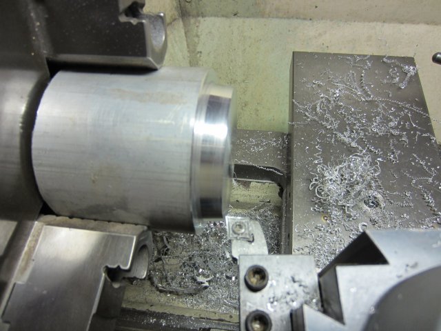
Now it starts to get a little tedious again and messy.
I need something to gauge the taper, I chose my 4 jaw chuck, I could have used the face plate a lot lighter, only thought of that now!
It also necessitated the removal of the locking pins from the chuck.

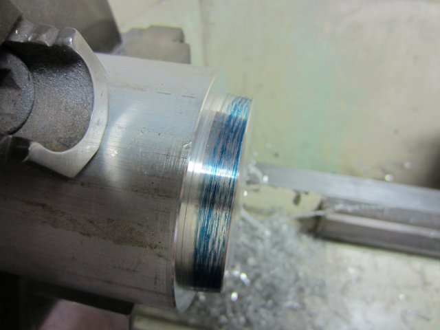
Now it is just a case of seeing how well the taper fits. Using engineers blue and moving the compound slide accordingly.
The compound slide needs only very slight adjustment. To help I place a dial gauge on the compound slide to help me with the slight adjustment. I had to make two adjustments before I was happy.

Then I got this near enough.
I just cleaned up the outer diameter.
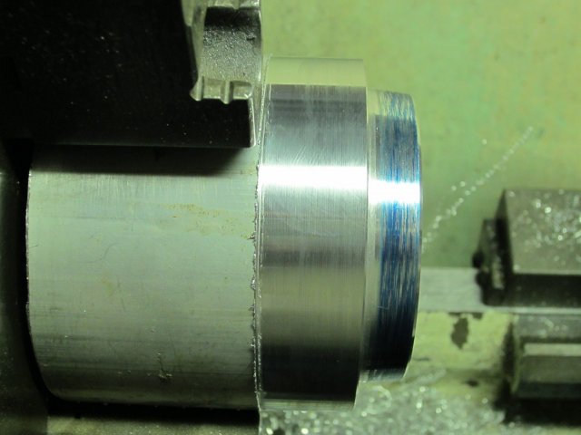
And thats the taper gauge done.
Just have to get the engineers blue off my hands, face, glasses, and my brand new camera
tis messy stuff.
Now to start the adapter plate proper.

DaveH


