Chuck, Thanks for checking in

- Like Bernd said, it's mostly used for the speed differential in cornering. On real trains, in a straight line, it also helps to keep the engine and rail cars from snaking around thus saving wear on the wheel flanges and track insides, as well as providing a more comfortable ride for passengers (think "horizontal" sea-sickness). In the model world, we don't care about the passengers, but it does help to eliminate some running friction - something my first loco with flat wheels suffers from quite a bit.

Dave, it is a bit warmer

. Life was generous with me; I actually received 3 brain cells - but I didn't receive good looks, good luck or any of that stuff
2 Brain cells are used for day-to-day living; the third is reserved for matters related to the fairer sex; that one's not allowed in the shop at all
- it causes havoc and nothing gets done! Besides, without the looks, luck and all of that, the 3'rd cell is permanently in overdrive on it's own mission
Thanks Dean. I just hope it will work with my modifications...
David, thanks

- when this one's done I'll take a note from your book and build a Stirling - well after making some tooling and possibly attempting a fairly unique engine build...
Thanks Allan
- There's quite a lot of Crackers on HMEM - Shred's is particularly nice and Tony Bird has built some very well-running variants of the Cracker. The plans are available from
John-Tom. The basic Cracker plans are extremely simple and lends itself to the builder's imagination, but I wouldn't recommend the Cracker as a very first project - exactly because of that, as well as some construction and assembly details that are not clear from the plans.

Glad you like Namibia; I go to Hardap once or twice a year for a weekend fishing trip; nice big carp and really big catfish in there. If you did Swakop/Uis/Etosha, did you go through Damaraland - Stunning over there. Around Swakop a trip to the Moon Landscape and welwitchias is always a winner. The Namib desert really gets under one's skin.
And
- I'm not surprised the people could make a bakkie tire fit a Corolla - over here bakkies and Corollas are pretty much the bread-and-butter transport...

Nope I don't know Dudley... Though I might have met him somewhere along the line in the local watering holes; I'm TERRIBLE at names!
Well, this morning my engine-building brain cell farted... After waiting for the stink to clear, and using
Charlie Docstader's Valve Gear program for checking things and running simulations with new dimensions, things looked to be on the up-and-up and good to go.
For the port block, the steam and exhaust ports needed to be moved lower to use available space around the boiler. Seeing as I'd have to do some fairly deep-drilling in the port block to, I decided to make the engine a double-acting rather than the single acting oscillator the plans show. The new design needs a thicker port block than the plans - preferably about 4m thick. I don't have 4mm thick brass plate, but a while ago I bought a ~4mm thick and ~200mm diameter phosphor bronze "washer" from my local supplier at a whim (and good discount!). A bit sawn from it:
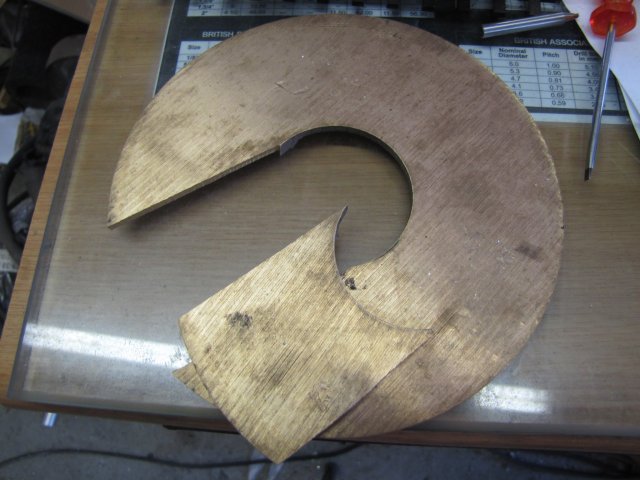
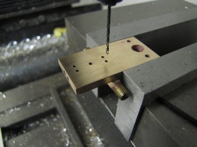
After more sawing, I had about a third of that section cut out - which was then milled to the engine port-block size and laid out. Then I started drilling some port holes:
2mm drill for 3mm deep, then 1.6mm drill 20mm deep
All the port holes were drilled to intercept the steam passages; I made an oops on one and drilled right through the port block

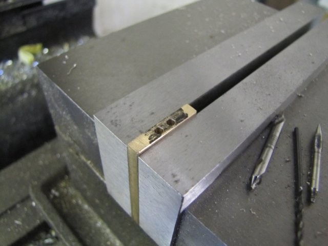
- fortunately where a bit have to be soldered on. The back of the port block, showing a lot of scars from over-vigorous de-burring (I forgot that PB will "grab" a drill bit - even if twirled manually - hence the scars around the big hole) - but more importantly the broken through port hole, a line to mark the center through it, and two groups of four punch-marks around the line:


Not up to my normal standard - I'm actually feeling bad showing such a bad-looking part. Mister's Moderator, can we please get an "Embarrassed" Smiley ?
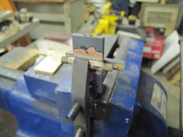
I needed a steam and exhaust connector to the port block, and all this faffing around was to get those down to a level where there would be space around the boiler to make those connections. The original plans call for a connection soldered behind the top port faces - I don't have that space - so I moved it down. A bit of 5mm hex brass was turned down and threaded M5 on each end, with a nice 90 degree countersink in the "steam" side (more on that later) and centre drilled at 2mm for about 12mm deep each end while on the lathe. Now the reason for those punch marks... The mentioned hex brass is to be soldered to the port block. Ordinary soft solder (electronics lead based type) could work, but I prefer silver solder (or hard solder or silver brazing) around steam bits. The silver solder (and flux) needs a gap to wick through, and the punch marks raises some high spots to allow just for this. A bit of soldering with a plumber's torch later:
After a quick pickle in warm citric acid (~10 minutes) and a rub-down with scotch-brite and another rub of the port face over some 800 emery, the block looked better and I could drill the bottom port holes through into the connector - this time without breaking through the back side

:
I love my camera; it shows all the bad detail - even on a reduced photo
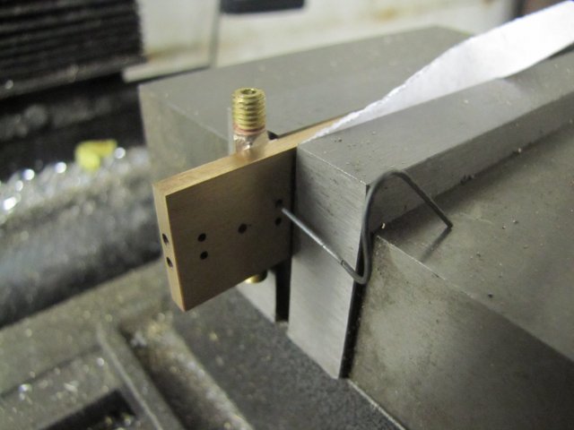
And a final drill through from the port connector sides using a "wiggly wire" to feel when the drill bit comes through:
Finished port block - back side:
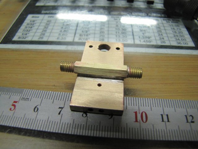
And piston side - dings and all; fortunately there are no dings where things matter
:

, Arnold


