Despite not having any pictures for this post, I think it is about time I make an intro to my next project as it is spilling into other threads. I`ve now got the Stuart 10V running very nicely and I`ve recently got the Webster IC Engine running to a seemingly acceptable level (I`m chuffed with it running!!), I`d like to move onto my next project - which actually is the first project I ever started!
Back in 2003/04 the professor and my tutor at Uni was mad into Patek Philippe watches. He clearly must have been on a great wage packet as their cheapest design, the Calatrava starts at many thousands of pounds. He had a couple of calatrava’s as well as a few grand complications!

Hoping to one day be on those dizzy heights (don`t worry, those thoughts have now permanently been crushed!) I had a bit of interest. Because Patek make hand made watches they after show images of their production shops and this brought out my hidden engineering interests. Knowing I couldn`t buy a Patek, I purchased some old pocket watches off ebay to take apart (Smiths for those interested). I later found out it must have been total luck, but I managed to fix one and suddenly thought I was a clock maker. I decided to buy a Unimat 3 lathe off ebay that I somehow won at a fantastic price (I made a few hundred pounds on it when I sold it!). I made a few posts on the NAWCC (National Association of Watch and Clock Collectors) forum and a kind chap over in Yorkshire invited me around to see his Unimat 3 mods and how he was setting up for wheel cutting ect. In his home I noticed an ME article showing John Wilding who had just finished writing his plans for Dr Woodward's Gearless Clock and was posting them in Model Engineer mag. Being a fool, I ordered all the materials, purchased the copy of ME (which was actually his second post, I`d missed the first episode). I asked my dad for some help and one Saturday morning we drilled 3 mounting holes for the brass back plate and failed when it came to soft soldering 3 washers on the back!!! I realised very quickly that I didn`t have the skills to make a clock and the materials and lathe were sold.
So now in 2011, with a couple of years experience behind me, I`m going to give this another bash! I recently ordered all the brass plate and received this a couple of weeks ago and I`m just waiting on the remaining materials, mainly imperial bar stock to arrive from College Engineering Supplies. I`ve also taken delivery of a length of nylon cord and some 0.006” spring steel. Last week while on holiday, I appreciatively took delivery of some 1/8” ID bearings from Clive off Madmodder! The only material which I managed to miss off my orders was a 12” length of 2” dia steel. I took my Grandma her birthday card on Wednesday evening and asked her if I had left any materials at her house from the clock (they had been storing it before I sold it). She called me up because the piece she had was too heavy – the only thing for some bizarre reason I did not sell was the 2” dia, 12” length of steel – freaky hey?!!
This is the clock:
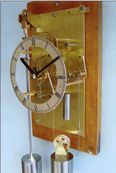
Dr Woodward originally wrote about the design in his book – My Own Right Time. Sadly I just not prepared to pay £40-50 for a copy of ANY book which seems to be what this one dictates. I have of course purchased John Wildings lovely write up of the plans and build process. He mainly cuts the clock using a Unimat, I`ll be following his methods unless I can utilize my small mill to better effect which he doesn`t use.
I should state right away that this build log has be written already by the notorious GadgetBuilder who details fantastically his build of this clock. He has made some excellent modifications of Wiliding’s design, especially the automatic maintaining works. Unfortunately I`m not confident, intelligent or daring enough to deviate from the plans other than a couple of fasteners where I`ll be using metric instead of the specific BA series.
http://www.gadgetbuilder.com/GearlessClock/Gearless_Clock.htmlThe clock uses a really unique method to run. A series of colliding pawls, hooks and rods give the pendulum an impulse, with the energy provided by the large weight.
Until I have pics to explain in more detail, the best way I can explain is:
There are two main aspects, the running train and the daisy motion. I`m going to start back-to-front and talk about the daisy motion first. Basically the “clock” mechanism rotates a main arbor once each hour – the minute hand is connected to this. The daisy motion is used to convert that 360 degree hour spin, into a 1/12 of a turn for the hour hand. Here is a youtube video made by gadget builder:
This is a really neat and novel idea allowing you to generate your hour movement from the minute movement – remember, without gears!! The smart thing is, a taper pin is removed and the entire daisy motion mechanics can be removed! This is why I mentioned this first, that just leaves us with the rest of the motion works.
Probably best to look at gadget builders explanation but here goes:
This clock only receives an impulse to the pendulum once every 60 seconds! This means everything involved with the count wheel must be very low on friction. Look at the pendulum and you will find two brackets. The upper one catches a tooth on the count wheel (the top wheel that looks like an escape wheel, NOT the pin wheel) and the pendulum is of such a length that in 60 seconds the count wheel goes around once. I`m wondering if a minute hand could be attached to the countwheel??
You probably can`t see in the photo, but one tooth on the count wheel is slightly deeper than the rest. When the pawl on the pendulum drops into this tooth, it pulls a lever down at the rear of the wheel. This lever has two section a bit like this “ > “ so as the top lever is pulled down anticlockwise, the bottom lever also moves down. This bottom section pushes down on the bottom “impulse pawl” of the pendulum (the pawl connected to the bottom bracket of the pendulum rod). This actually pulls the count wheel (the pin wheel) anti-clockwise for a second but at this point the weight which is wrapped around the count wheel to pull it clockwise, pulls the wheel back clock wise again. Now however, the levers are not bearing down on the impulse pawl (the count wheel pawl is back in a normal small tooth) and it is free to lift up out of the pin it is holding (the pin wheel also moves through a gate and moves forward by one pin, i.e one minute!!!!) but now the pendulum is at a higher position again – i.e the pendulum has been given an impulse! The pin wheel moves on by one pin every minute and therefore with 60 pins, the pin wheel does one revolution every hour – the minute hand!
Add the daisy motion to this and you have your minute and hours!
I`m not going to rush this but to be honest, with no gears the parts don`t look overly complex so I expect to make good progress. I expect like I have experienced with my Webster IC, most of the time will be in the troubleshooting, getting it to run!
Pictures will hopefully be following!
Chris


