Hi Rich,
The spacers are actually the reason I drew the assembly, it just did not make sense to me. After drawing it all I actually found that with the normal bearings, spacers and gear assembled, the distance between the insides of the two bearings was 2+mm more than the registers in the housing. With the taper rollers it ends up 0.5mm to short, makes one think.

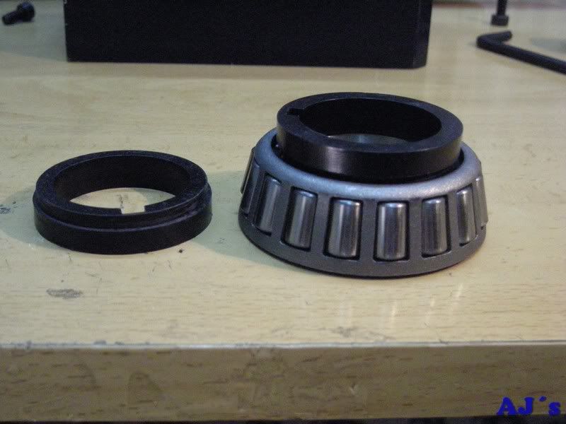
I will also be making a fatter rear one from mild steel for the rear lip seal to ride on.(still need to get the length once all is in its place)

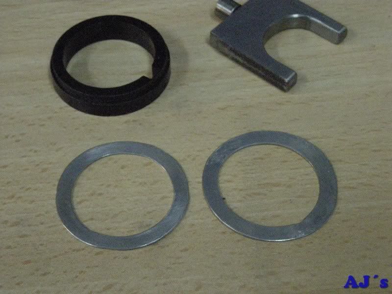
The spacers next to the bearings needed a step cut to clear the cages. They were machined with the CNC router.
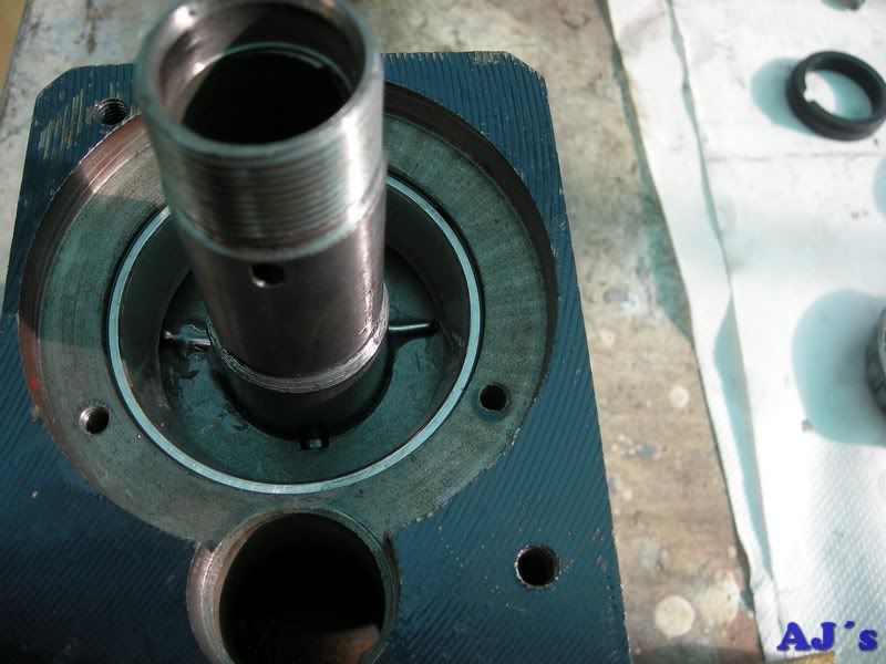
Everything was given a thorough cleanup, there was a lot of casting sand still embedded on the inside surfaces of the housing. The hub on the spindle where the new seal will ride was polished.
All ready for assembly.
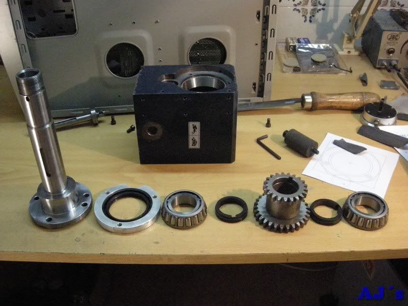
It was then all assembled dry and alignments checked. I took some measurements to make two spacers for the lay shaft to act as stops, preventing over travel of the change gear.
Next I used a method we use in the adjustment of taper bearings in machine transmissions. Between the gear and last spacer two pieces of soft solder is trapped, the preload is then adjusted and all disassembled. By measuring the thickness of the flattened solder the spacer thickness is determined.
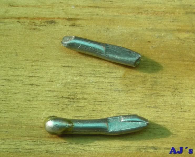
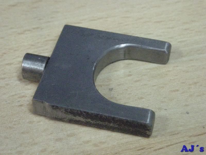
Here it averaged out to 1mm, so I made two 0.5mm ones from alu sheet to go both sides of the gear assm. Also rounded over the ends of the shift fork to prevent any foul-ups. A small relief was also made in the fork to clear the shift lever shaft.
Hopefully final assembly is next.
Abraham


