Thanks Nick, this has been a learning experience all the way along. Hi all, getting close to a finished engine, so here's today's installment.
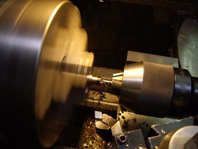
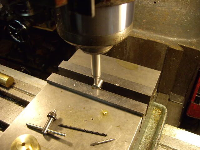
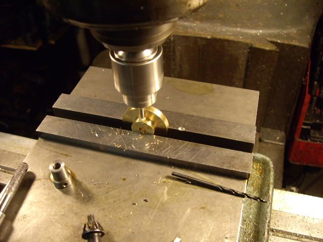
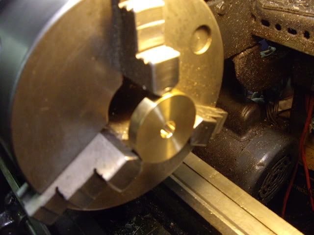
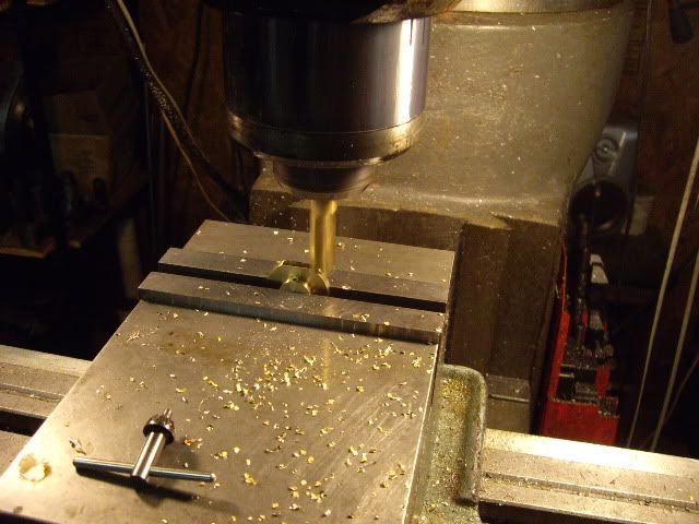
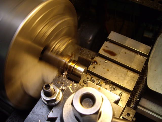
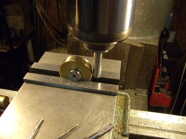
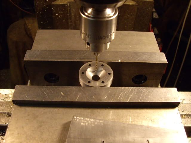
a piece of brass round has been bored out for a flywheel, so I've turned a piece of steel for the hub, and I'm center drilling it in preparation for drilling and reaming to fit the main shaft
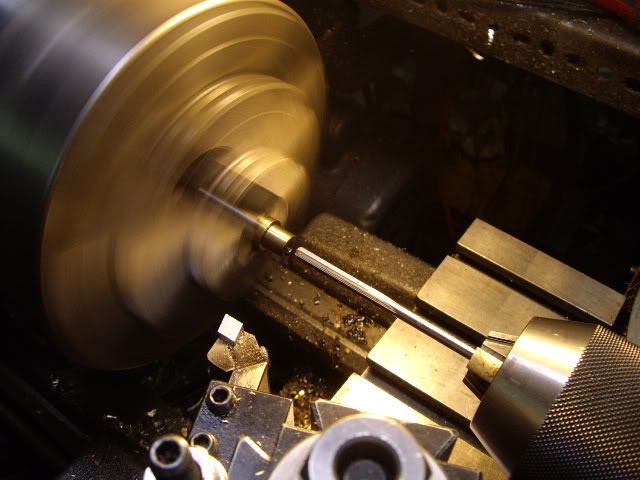
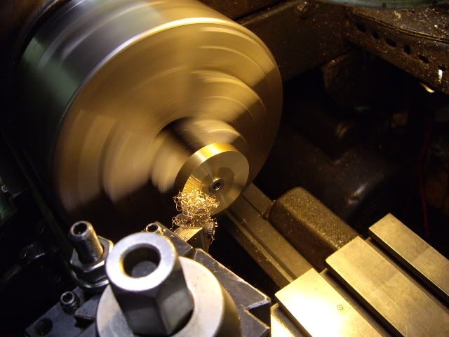
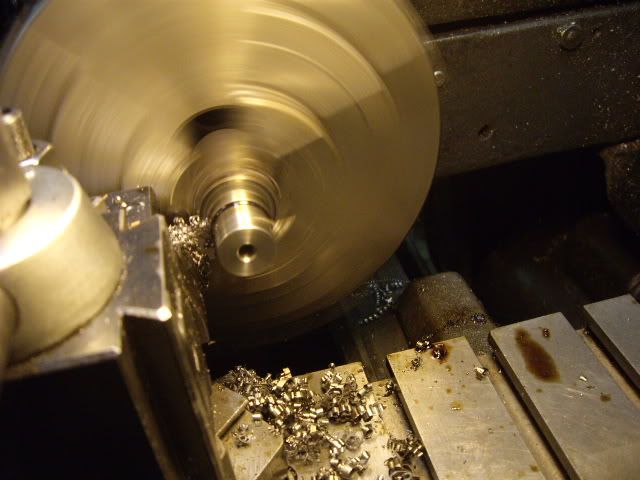
I missed a picture of drilling, but here's reaming it out to three sixteenths
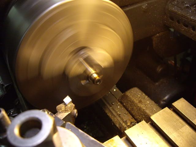
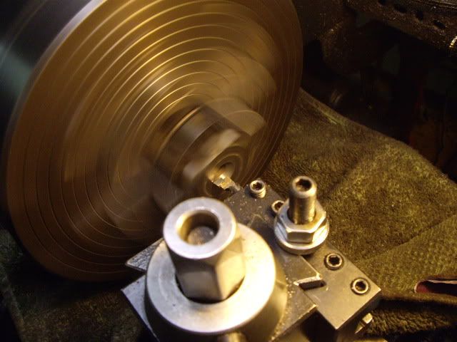
facing off the end of the hub and ensuring the shoulder is square with the bore
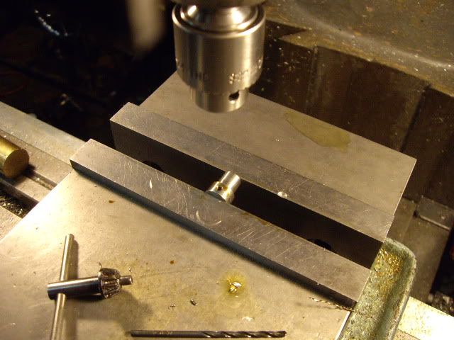
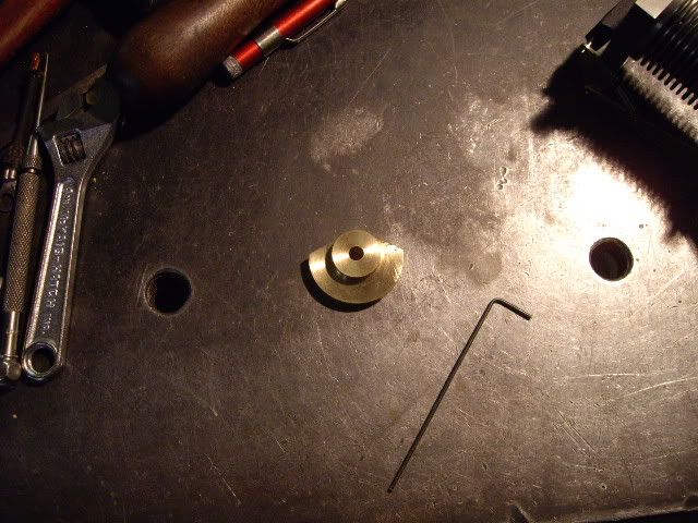
setting the hub up for grub screws, I like to put two at least, and at 90 degrees for security
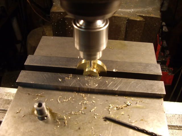
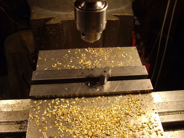
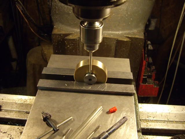
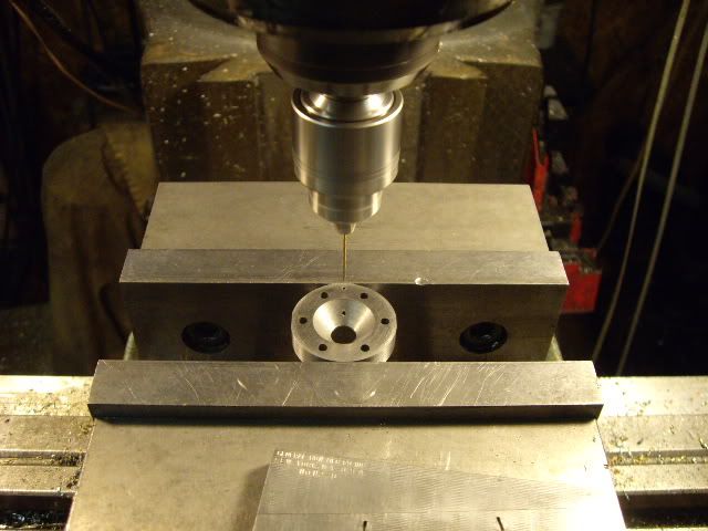
centering the spindle over the hub
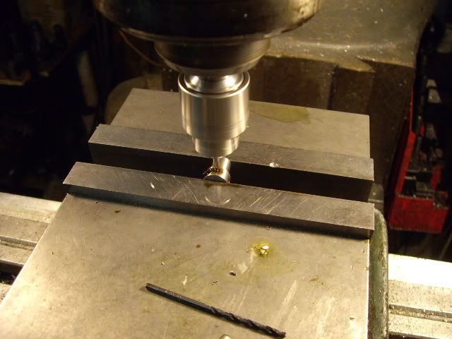
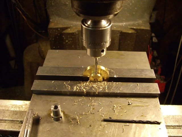
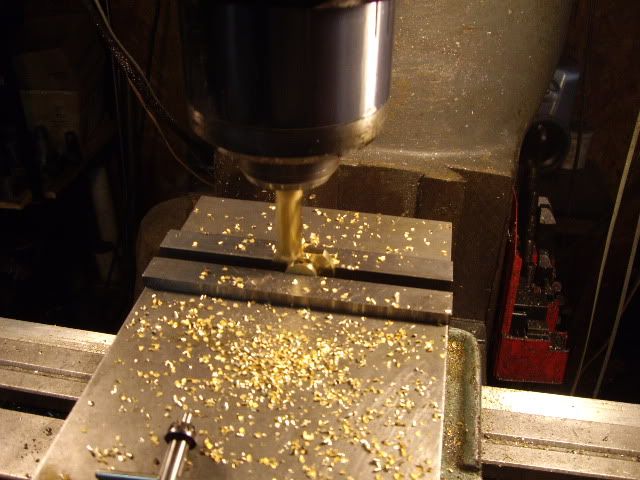
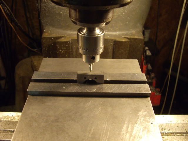
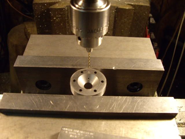
center drilling the first grub screw hole
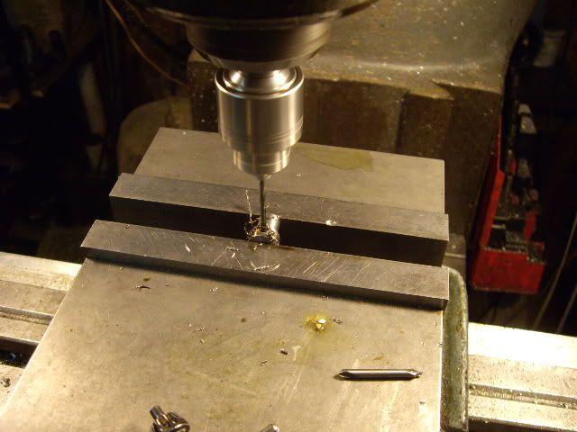
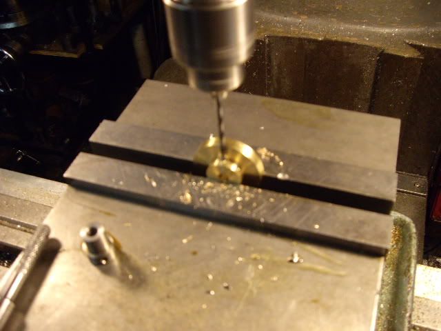
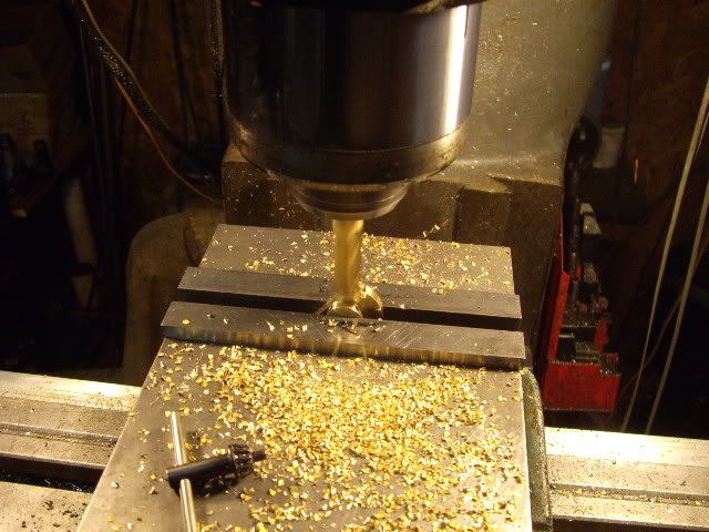
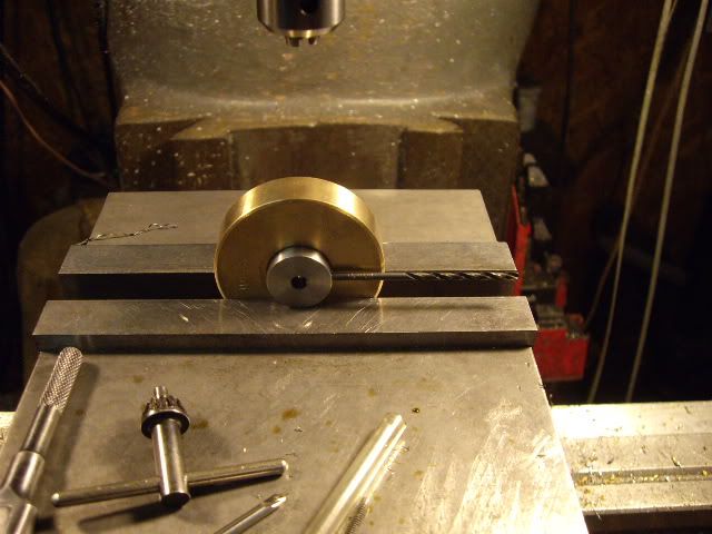
tap drilling the first hole
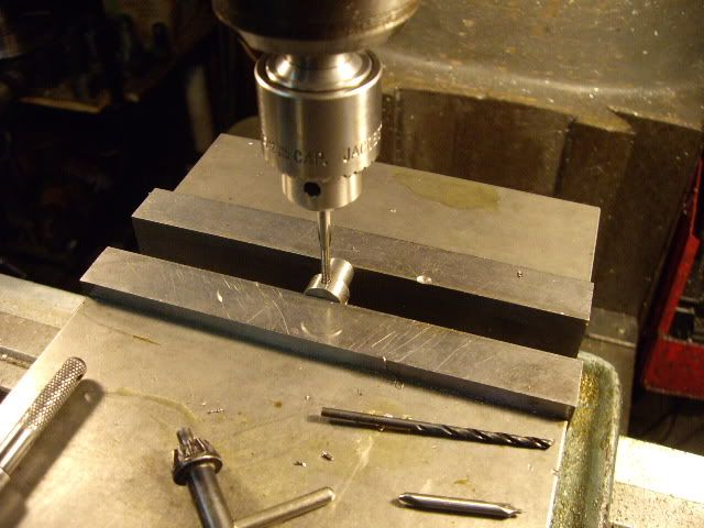
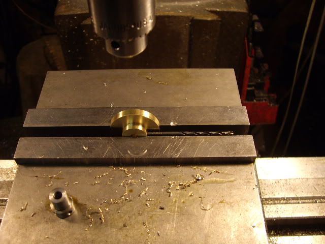
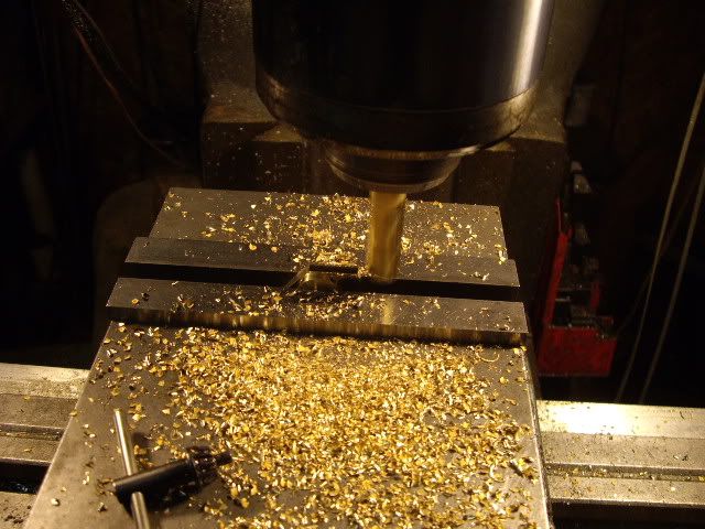
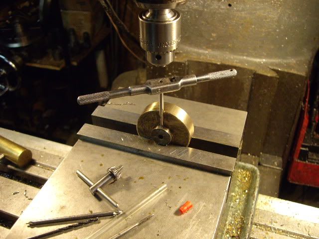
tapping the first hole, the second hole is treated the same, using the tap drill in the tapped hole as a guide to getting the second hole at 90 degrees from the first
having centered up the cam blank, drilling the center hole for the first grub screw
tap drilling the cam blank
tapping the grub screw hole, 4-40
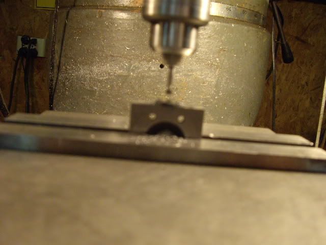
setting up for the second grub screw hole, note the tap drill sticking out to the right
center drilling again
flywheel bored and faced for the hub
hub pressed in, facing off the other side holding the hub
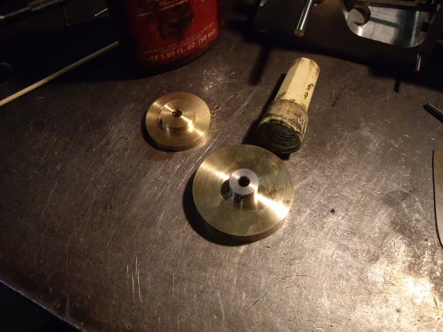
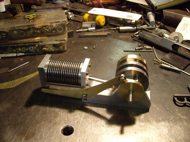
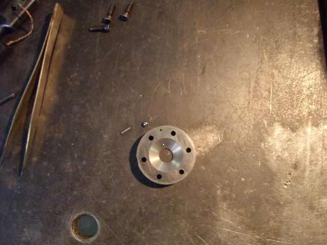
flywheel and cam, ready for mounting on the main shafts
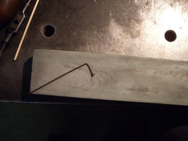
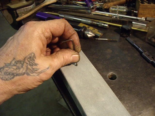
with a grub screw on the end of the allen wrench, the cup is stoned flat to keep from scoring the shaft I will have to adjust the cam some, and don't want the shaft all buggered up
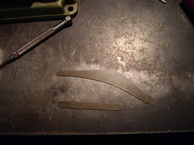
valve lever blanks, ready for hole drilling
drilling the first of many holes
filing the first of many radii on valve train gear
the main valve actuating arm with its follower bearing riveted in place
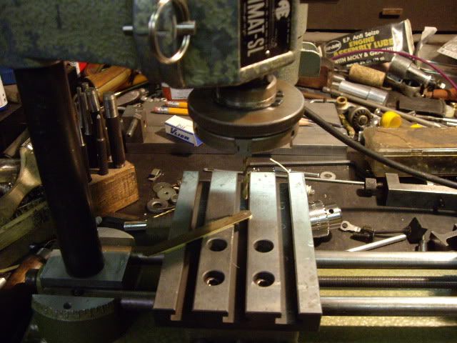
two connecting link plates, clamped for drilling holes
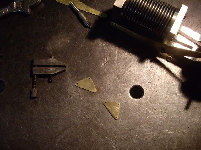
holes drilled for the arm, the valve pin, and for the pivot rivet to hold them to the valve levers
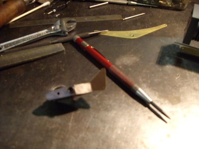
setting up to cut off the rivet, a brass brad from a box of picture hangers
cutting off the rivet, draw sawing for control
the main lever in place with the valve link riveted in place
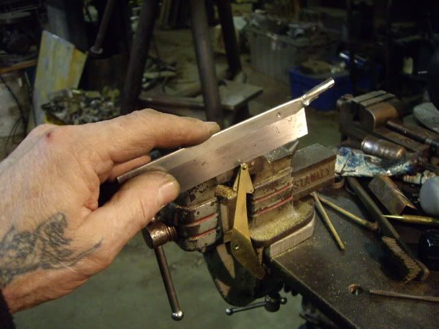
the cam back off the engine, getting a flat milled so I can set the valve at its open point
getting the flat down to the hub diameter, minus a hair for filing
with the valve lever in place, some idea of location established with the flat, drilling the generator brush for the valve pin which will carry it. The pin is about .093 diameter, with .040 pins machined on each end, it came like this out of a CD player or something, and happened to be the right width for the head, and already have pins machined
having set up the valve, the cam is removed again, to get its second flat milled, to make it proper timing
several passes later, the cam is on its final cut
the cam, ready for some filing to remove the sharp corners, and make for smooth valve opening and closing
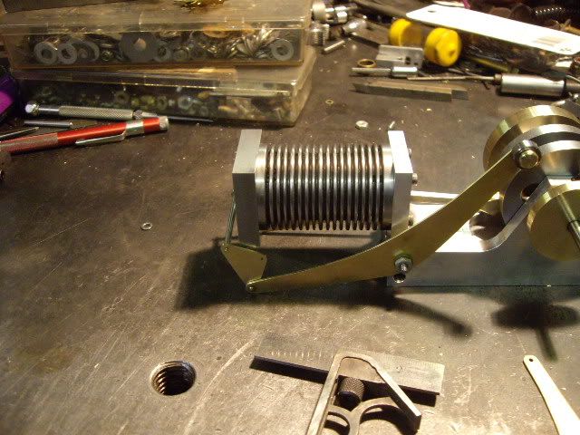
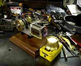
not quite done, but ready for a trial run. You have to test things like cam timing and how things like the linkage work.
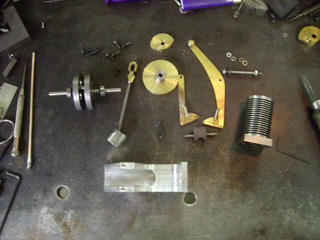
engine disassembled for drilling mounting holes, all the parts spread out
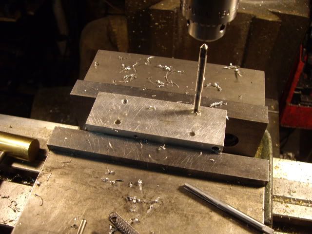
drilling the mounting holes for mounting on some brown stuff
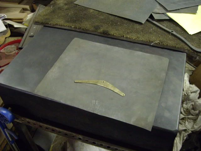
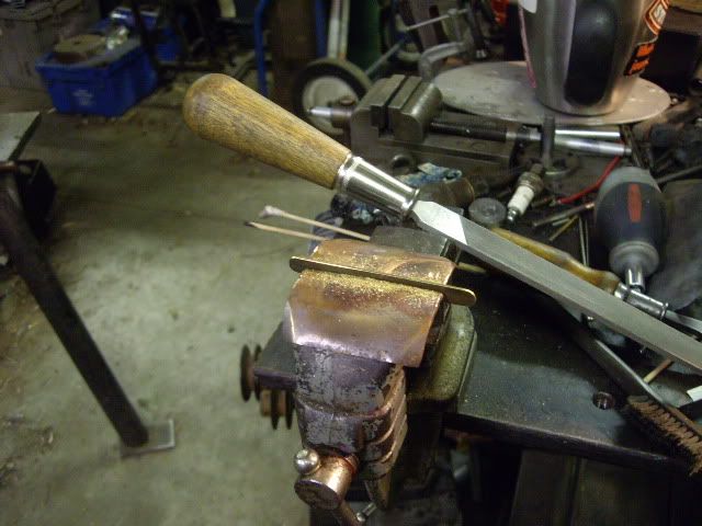
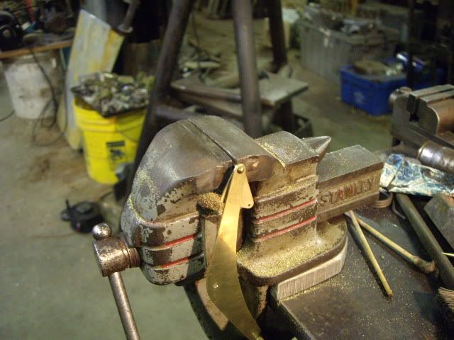
after the first run, I found the levers of the valve gear wrong, and remade them a quarter of an inch longer so the valve would stay flat against the head, something it quit doing in the first run. I didn't take pictures of cutting out new brass levers, but do show how I finish the flat pieces for a good finish.
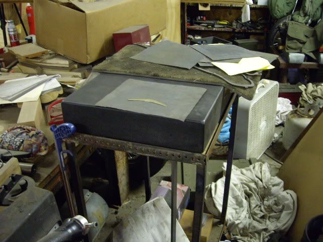
another view of the surface plate, 18 by 24 by 4 inches
I decided I needed more flywheel, so I took a piece of steel shaft, a bronze gear with its teeth eaten away, and made a hub, then pressed on the old gear, and turned the o.d. smooth
cutting off the hub
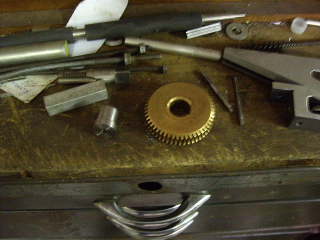
the hub and old gear ready to be mated
centering for drilling grub screws
using a long center drill, center drilling the hub
after tap drilling, tapping the hub
setting up for the second grub screw, same as the first
again, stoning off the cup of the screw
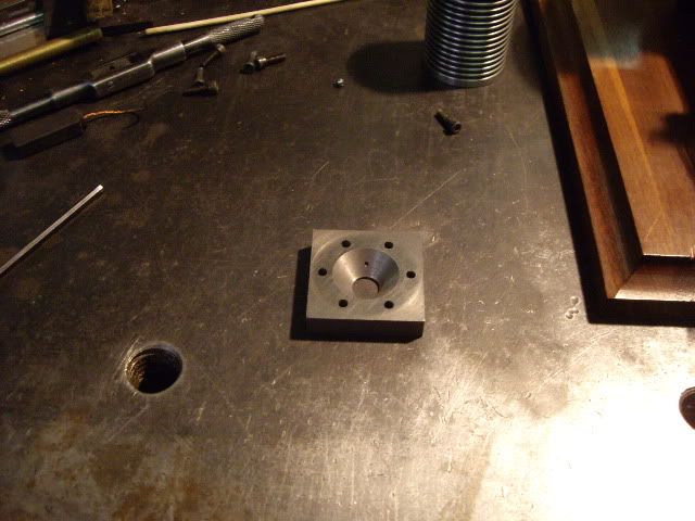
with the head at .300 in thick, I found I needed to bore a taper as the straight port seemed to "quench" the flame as it went in, the angle is such that the diameter of the conical port is bore diameter at the head surface, and has about .020 in thickness on the face end
having seen several such engines with pressure relief valves of sorts, I decided one might help the running of this engine, so I used a #1 center drill, and drilled in the top center of the head till the tip of the center drill just pierced the port. I'd found a ball bearing which measures .112, which dropped nicely into the .125 hole the body of the center drill left.
another view of the head and the center drill. I also drilled a .140 hole deep enough to leave about an .100 in of the center drill hole, the full taper seat of the center drill for the ball to seat on, but with plenty of room for excess air to escape
here you can see the tapered port, and the pressure relief hole just entering it
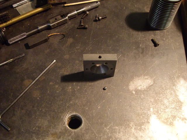
another view of the head, relief hole and check ball
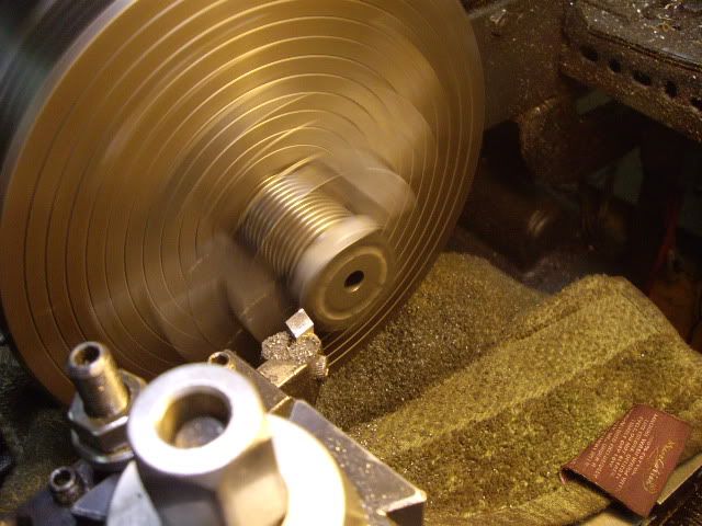
I had left the head square for surface area for the valve, but found no need, so turned it round to reduce the mass of the head
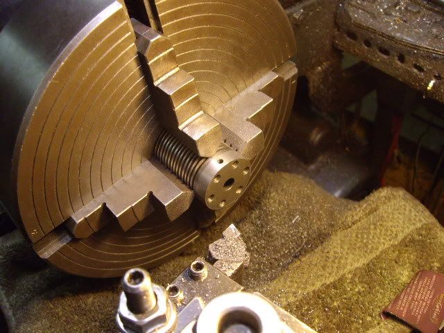
I bolted the head on the cylinder, centered it up, and turned it down, here it is done, with the relief port on top
I almost lost the ball testing to see if it worked, and put the head in the mill vise to drill a hole for a pin to retain the ball. The pin hole goes through from the cylinder surface, through the relief hole, and just starts in the front surface of the head, it is .042 as I have some .041 spring wire to use for the pin.
drilling from the cylinder side
drilled, ready to clean all the swarf out of tiny holes
head, check ball, and retaining pin
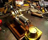
this is the first run after fixing the valve gear, but before the check valve was added, this run was the reason for the check ball.
And here is the last run of the engine, with the check ball, and everything completed except its own burner, which will probably be modelled after John's butane burner from his flame eater, as I like the clean burning and the ability to adjust the flame and thus the speed. I hope you all enjoyed this as much as I have.


Cheers, Jack


