I want a small turbine, and the great Mr. Elmer Verburg published plans for one. My build is loosely based on his design, and about the same size, but I'm taking some liberties and doing some things my way - which might just bite me in the back

Having said that, I feel it is also VERY important to stress that turbine builds should not be taken lightly. At high pressures and very high rates of rotation even a small turbine can be a little bomb waiting to disintegrate - it is NOT the type of engine for people who are inclined to want to test engines "to destruction". My aim is to build a small breath-powered turbine for display purposes - nothing more. I really hope I can get it to run on breath power, but therein lies a problem; if it can run on breath power, it will be a dangerous engine if used on high pressure compressed air. From my research, a turbine needs to be built pretty darn accurately; the rotor needs to be as balanced as possible and tolerances should be kept tight.
I wanted to post this up yesterday evening, but weariness overcame and I settled for a quick dinner and bed instead
A week ago Sunday afternoon I started off with a block of aluminium for the main engine body. This is my first deviation from Elmer's plans - which call for some pieces bolted together. I want to practice some milling techniques, hence the solid block. It was first flycut square on the mill:
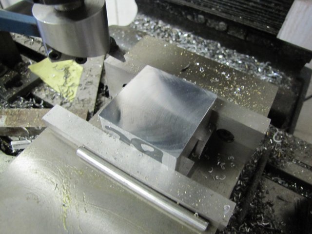
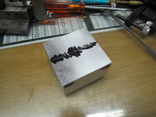
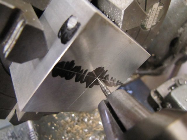
Then marked out:
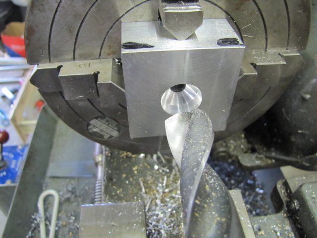
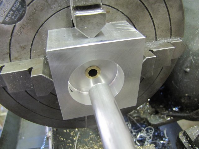
The main "steam port" was drilled out 2mm to the top center of the block and then opened up to 4.2mm to be threaded for a 5mm steam connector. Then the block was centered up in the 4-jaw on the lathe. You can see the hole for the steam connector on the side. I'm using a sharp pin in the tailstock drill for alignment; this is accurate enough at this stage and gets me to within 0.02mm. I still can't center punch a hole accurate enough to use a DTI and center finder to beat this

:
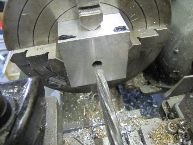
That lot was then center drilled, drilled 7.8mm and reamed through to 8mm:
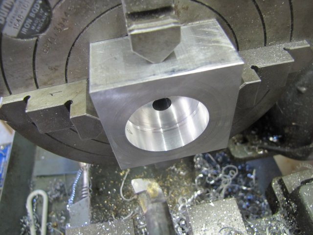
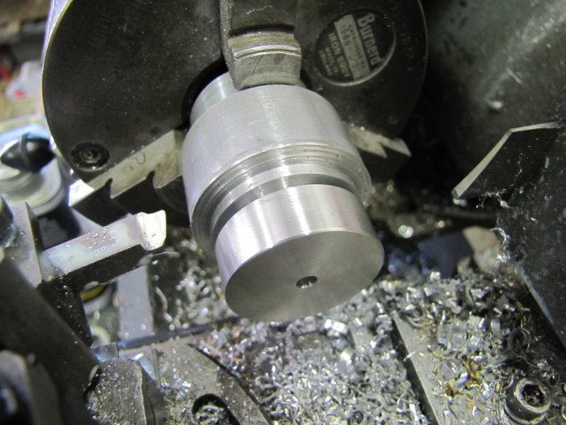
Then drilled with a 19mm drill to a depth of 12mm at the drill's tip:
And bored out to 32mm diameter 12mm deep:
I then changed chucks - without removing the engine body from the 4-jaw, I fit the 3-jaw.
Elmer specified 2 bushes pressed in from both sides; I went for one bush - turned from some hex brass - turned to 8.02mm OD and drilled to 5.9mm and ready to be parted off:
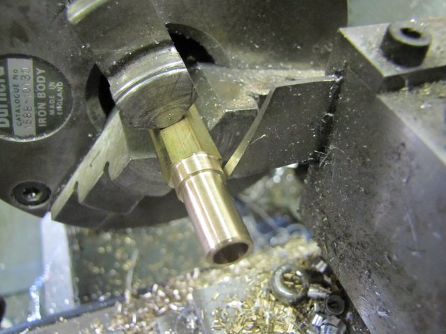
After parting, it had a 0.2mm thick flange - intentionally:
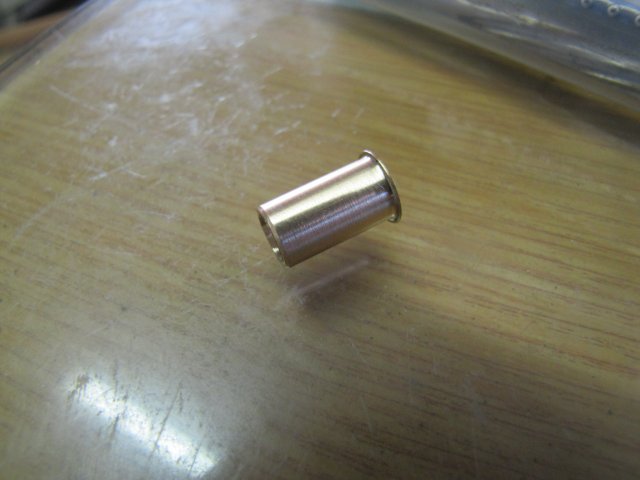
I then re-mounted the 4-jaw and pressed in the bush with a bit of aluminium gripped in the tailstock chuck - with a smidge of bearing retainer to make sure it would stay put:
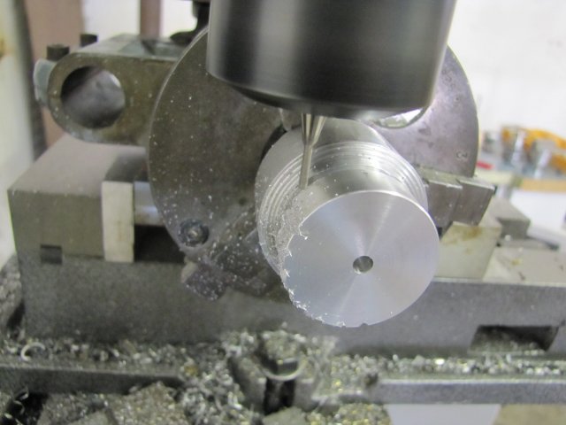
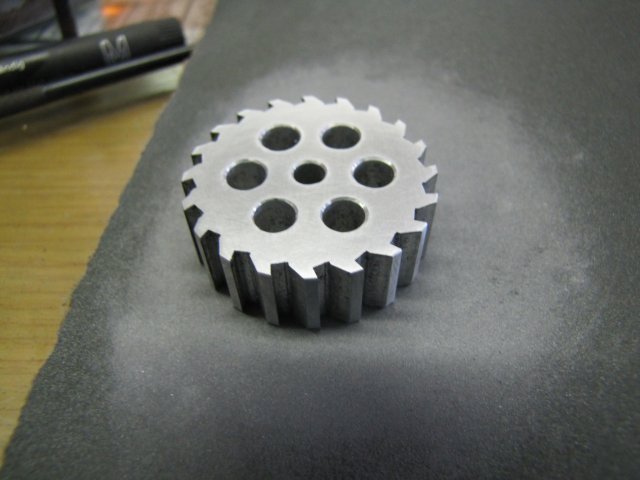
I didn't get anything done on Saturday, so on Sunday I started off on the rotor. Some oversize aluminium turned down, and parted down part-way:
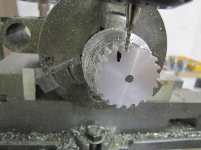
With the dividing head mounted in the mill vise, I started whittling away at it - at an angle chosen by eye:
My starting cut was a bit aggressive, and I broke one of the Richon Tools cutters on it. Purely my fault; a 2mm HSS cutter can not take a 2mm depth of cut at a silly feed rate - and 1200RPM is a bit slow for it as well

- So I settled back to an acceptable 0.6mm DOC and a sensible feed rate; I can't do anything about the spindle speed; that's max for my mill.
A little while later, and with a new angle on the cutter:
It would look (and maybe function) a lot better if I had a 2mm ball-nose for this. I'll include that on my next order.
On to the rotary table with the chuck, and poked some 5mm holes in the rotor to lighten it up a little:
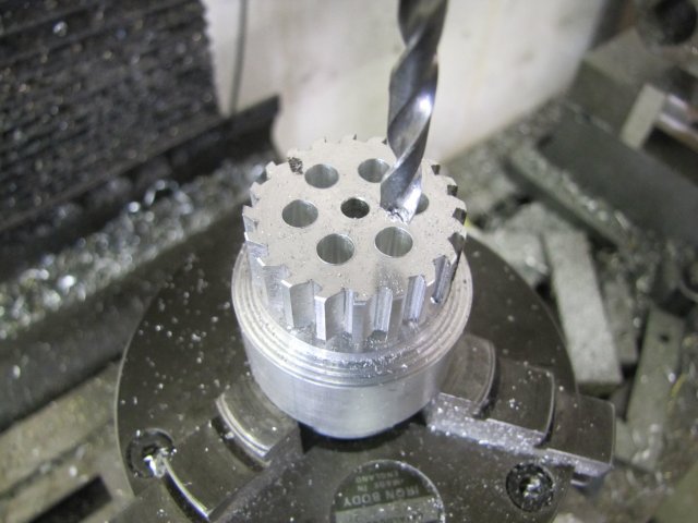
Finally, back on the lathe, and drill 3.9mm deep enough for the 4mm reamer to ream out the center hole:
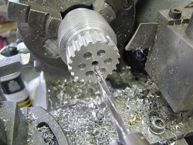
Part it off:
A year or so ago, parting off was one of my worst nightmares, and a challenge I set myself to conquer. It's not fully conquered yet, but improving all of the time. This was the result of the above parting - after I used a countersink to clean up the holes:
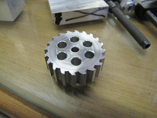
There's still a lot of rough bits, but a heck of a lot better than what I did in the past, and a lot less brown stuff in the pants!
A quick rub on some 600 emery, and no-one would be any the wiser - except for everyone reading this, that is
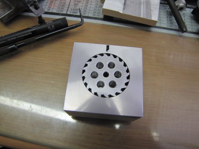
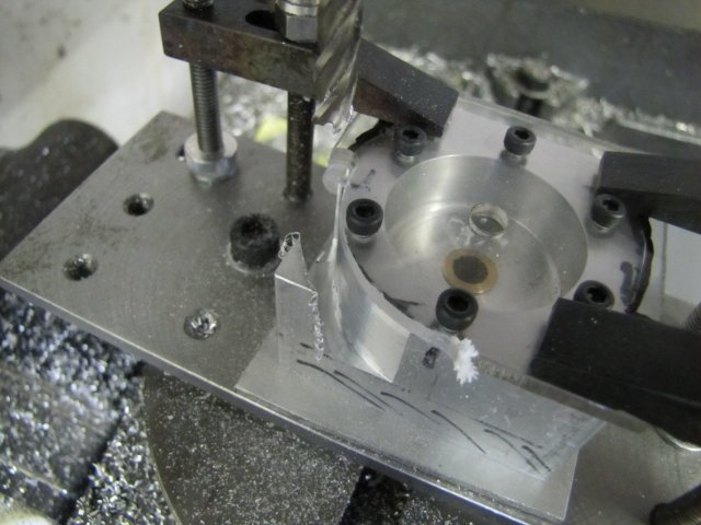
It fits nicely in the block as well:
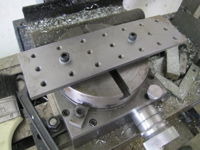
There was a short hiatus on tooling work to mount my tooling plate on the rotary table. A pair of high tensile M6 cap screws with the back section turned down far enough so that they can screw through the tooling plate with washers, and then spin freely so that they can pick up T-nuts in the rotary table slots:
Mounted:
Back to the engine, and I started on some mounting holes for a clear perspex cover for the engine - with 2.5mm holes drilled for threading M3:

And a bit of fettling with a 6mm mill:
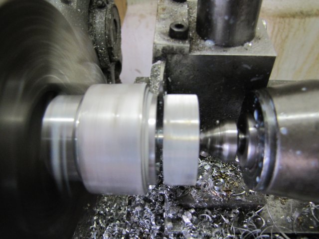
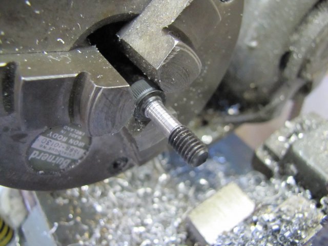
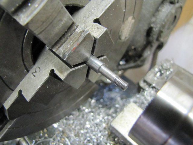
There's quite a bit of fettling left to do, but time caught up, and I quickly made the main shaft to check things out. My collet chuck is pretty accurate, but not good enough. A turbine needs to be dead on, so I clocked a bit of 6mm silver steel up in the 4-jaw - with less than 0.005mm (that's about two tenths of a thou for the imperial blokes) run-out on the end, and turned it down to 4mm to fit the rotor, and then threaded it M4 with a tailstock die holder to take a nut:
Where I ended up for Sunday:


- at least, if I blow in the hole, it turns, but it looks like it will need an exhaust passage as well.

, Arnold


