Author Topic: ML10 Head Removal  (Read 14950 times)

Offline HS93

  • In Memoriam
  • Hero Member
  • *****
  • Posts: 788
  • Country: gb
ML10 Head Removal
« on: December 27, 2010, 03:40:04 PM »
I  need Help , I have to remove the head of a ML10 so it can be transferd to my home, I want to break it down so it will go in a car easily as I will not be doing the first leg of the transporting, it WILL need to be able to be re fitted in the end. :doh: I am trying to get it in managable pieces so it can be lifted without damaging both the people and Lathe

thanks

       :ddb: Peter  :ddb:
I am usless at metalwork, Oh and cannot spell either . failure

Offline Brass_Machine

  • Administrator
  • Hero Member
  • *****
  • Posts: 5534
  • Country: us
Re: ML10 Head Removal
« Reply #1 on: December 27, 2010, 08:11:28 PM »
Peter,

I am not familiar with the ML10... but if you were closer, I would go with you to help.

Sorry
Eric
Science is fun.

We're all mad here. I'm mad. You're mad.

Offline Bogstandard

  • Bogs Group
  • Hero Member
  • *****
  • Posts: 1107
Re: ML10 Head Removal
« Reply #2 on: December 27, 2010, 11:48:39 PM »
Peter,

You might find it is a little more complicated than that.

As far as I can remember, there are not a lot of bolts actually holding the head down, it is all the hanging on bits that cause the trouble, belt covers, gear quadrant and back layshaft that need disconnecting and/or removing before the head can come off.

Just ask the seller to strip it down for you, putting the bolts back into their original holes they came out of, just so things don't get confusing and making it easier when reassembling.

Give Jackie an extra Shredded Wheat and she should be able to carry it as is. I was amazed at what she carried when you dropped that stuff off at my place. Good things come in small packages, she is definitely a keeper, as will be your new lathe.


John
If you don't try it, you will never know if you can do it.

Location - Crewe, Cheshire

Skype - bandit175

Offline HS93

  • In Memoriam
  • Hero Member
  • *****
  • Posts: 788
  • Country: gb
Re: ML10 Head Removal
« Reply #3 on: December 28, 2010, 09:31:35 PM »
Thank you for the offer Eric, very nice off you , and John how do you think I get the cars on bricks, and after showing heir the post errrr have you got a good tyre supplier locally. :lol: :lol:
ill see what happens, having my anual proceure on the 30th so I will be going down earley in the new year.ill tell you John if they find Sooty. sorry for the joke non uk tv viewers. :dremel:


  :ddb: Peter  :ddb:
I am usless at metalwork, Oh and cannot spell either . failure

Offline joegib

  • Jr. Member
  • **
  • Posts: 15
  • Country: gb
Re: ML10 Head Removal
« Reply #4 on: December 29, 2010, 11:08:22 AM »
Hi Peter,

I have an ML10 so can add to Bogs's comments. First, I suggest you obtain a copy of the ML10 manual so you can study the layout. This can be downloaded from the Yahoo 'myfordlathes' group here:

http://groups.yahoo.com/group/myfordlathes/

It's the 'Files/ML10' section of the archive under the name 'Myford ML10 Manual small.pdf'. Note that you'll need to join the group first to access the archive but that should be granted after a day or so.

In the meantime here's an overview of the lathe assembly to give you an idea of the layout:
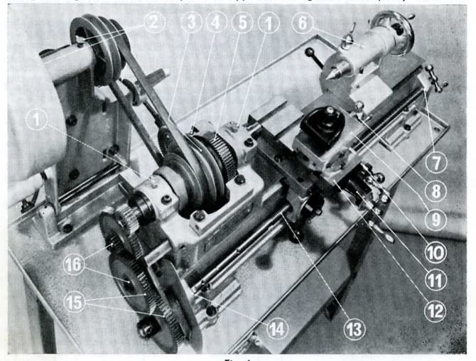


As regards disassembly, here's how I do it.

1. Remove countershaft pulley and changewheel guard covers. Each of these is simply held by a single knurled thumbscrew.

2. Remove electrical switchgear/wiring from its mounting points on bench/stand and lay it aside (main wire remains connected to motor). Remove motor from motor/countershaft assembly. Thus motor/wiring/switchgear forms one block for transport.

3. Remove tailstock by releasing locking lever and sliding it off the bed.

4. Remove headstock belt/pulley/backgear cover. Pull back the cover and this will expose the two boltheads securing it on top of the nearside headstock (clearly visible in the photo). Undo these and remove the whole cover assembly.

5. The ML10  bed slide is formed of a single broad male dovetail. The headstock casting is machined with a single-sided female dovetail seating at the nearside and this mates with the male nearside bed dovetail. The headstock is locked to the rear bed dovetail face by two lugs that apply pressure via bolts and setscews. Hard to describe but the setup and principle is obvious when you see the arrangement. (Sorry, I don't have a photo).

6. Release tension on the headstock drive belt by pushing the toggle lever backward. If you examine the toggle lever assembly you'll see it's held by an 'L' bend in the lower end which simply hooks into a drilled hole in the headstock. To the right of this hole (towards the tailstock) is the right-hand headstock lug described in section 5. Unbolt this lug completely and store it safely.

7. At this stage all that is holding the headstock and countershaft assemblies together is the toggle assembly and the untensioned V belt. Hold the countershaft assembly to prevent uncontrolled tipping and unhook the V belt. Likewise, unhook the lower toggle assembly from its hole in the headstock by pulling it rightwards. Now the countershaft assembly/toggle assembly can be unbolted from the bench/stand (it's secured by 4 bolts and nutted underneath the bench/stand).

8. Finally, undo the left-hand headstock lug and slide the headstock towards you straight off the bed (the belt remains captive).

9. Then all that remains is to unbolt the bed (plus raising blocks if present) from the bench/stand.

I'd echo bogs's comments about keeping bolts nuts washers safely i.e temporarily scewing them back into their appointed places for transport.

Process probably sounds a bit complicated but it's fairly easy once you've done it. Nowadays I can disassemble the lathe for overhaul in about half an hour. The weightiest item is the bed — maybe 70-80lbs. (Incidentally, I picked up the 'long', Speed 10 version of the bed last year and humped it from Salisbury to London via passenger rail and Underground on a trolley. I'm 64 and not especially robust so this little lathe shouldn't give you any trouble).

Re-assembly is mostly a reversal of the forgoing but points to note are:

(a) When fitting headstock to bed make sure the respective dovetail seatings are scrupulously clean — precise axial alignment of the machine depends on this.

(b) Take care that pulley alignments are correct using a straightedge.

Joe


Offline HS93

  • In Memoriam
  • Hero Member
  • *****
  • Posts: 788
  • Country: gb
Re: ML10 Head Removal
« Reply #5 on: December 29, 2010, 01:25:52 PM »
Thank you for that it is a great help, Ill join the groupe now and see if I can download it soon , but your explanathion should be enough to do it, it should help if we get any more snow as the car is rear wheel drive.

Peter
I am usless at metalwork, Oh and cannot spell either . failure

Offline HS93

  • In Memoriam
  • Hero Member
  • *****
  • Posts: 788
  • Country: gb
Re: ML10 Head Removal
« Reply #6 on: December 29, 2010, 01:31:34 PM »
In case I am not able to download in time what type of nuts are they Ie metric AF other as it is an old lath so I know what to take

Peter
I am usless at metalwork, Oh and cannot spell either . failure

Offline Bogstandard

  • Bogs Group
  • Hero Member
  • *****
  • Posts: 1107
Re: ML10 Head Removal
« Reply #7 on: December 29, 2010, 05:24:58 PM »
Peter,

I don't know the exact sizes, but this might help.

Termed as 'shifters' in engineering circles.


This is my 'short' collection

On the left is a right handed 6" Imperial one. The one in the middle is a right handed 150mm Metric version, and the one on the far right is a very rare Impetric 6"/150mm in the left handed style. It can be set for both Metric or Imperial, but being left handed, is rather difficult for right handed users to cope with.


John
If you don't try it, you will never know if you can do it.

Location - Crewe, Cheshire

Skype - bandit175

Offline joegib

  • Jr. Member
  • **
  • Posts: 15
  • Country: gb
Re: ML10 Head Removal
« Reply #8 on: December 30, 2010, 03:20:15 AM »
Hi Peter,

Per the manual the ML10 standard equipment is:


So it includes 2 spanners covering BSF sizes 7/16", 3/8", 5/16" and 1/4". Be nice if you can get the seller to cough these up. More importantly, the standard equipment mentions a "special" spanner used for the square-headed screws that lock the topslide swivel base to the cross-slide so politely insist that this is included if you can. You shouldn't need them for disassembly but eventually you'll need a set of Imperial Allen keys for various adjustments. As Bogs says, take some adjustable spanners with you in case you encounter the unexpected.

One last thing, the outline I gave earlier assumes your ML10 has the earlier standard length bed in which case the countershaft/motor assembly is mounted quite separately to the stand/bench. Later versions, the 'Speed 10' in particular, had a slightly different arrangement in which the countershaft/motor assembly was mounted on an elongated left-hand raising block which was extended back to support it. In this case you may have to vary the disassembly slightly but no doubt the seller will help.

Pipe up if you need any more help.

Joe

Offline DavidA

  • Hero Member
  • *****
  • Posts: 1219
  • Country: gb
Re: ML10 Head Removal
« Reply #9 on: December 30, 2010, 08:15:20 AM »
John,

...Termed as 'shifters' in engineering circles.... :bugeye:

Of course,  a REAL engineer would not allow them in his shop.  Not even the excellent Swedish Bahco ones.

But not to worry,  I also have two for 'emergencies'.

Dave.

Offline Bogstandard

  • Bogs Group
  • Hero Member
  • *****
  • Posts: 1107
Re: ML10 Head Removal
« Reply #10 on: December 30, 2010, 01:39:38 PM »
Little would you believe it Dave, they are 25 years old, and working as well as the day I bought them.

They hang in 'grab' areas in my shop, one shifter and one six inch rule, hanging side by side. It is marvellous just how often they get used instead of walking to my spanner rack to find the correct spanner for the job.


Bogs
If you don't try it, you will never know if you can do it.

Location - Crewe, Cheshire

Skype - bandit175

Offline DavidA

  • Hero Member
  • *****
  • Posts: 1219
  • Country: gb
Re: ML10 Head Removal
« Reply #11 on: December 30, 2010, 05:10:35 PM »
I mostly used mine when I was involved in factory maintenance about six years ago. Like you,  I found them more convenient than lugging a took box everywhere.

Dave.

Offline joegib

  • Jr. Member
  • **
  • Posts: 15
  • Country: gb
Re: ML10 Head Removal
« Reply #12 on: December 31, 2010, 01:09:14 AM »
Hi Peter,

Don't know if you've made your trip to collect the lathe yet but looking at the thread again, a further few points occur to me:

1. Although not mentioned as 'Standard Equipment' there is a further special item that came with the lathe — a non-standard Allen key whose short arm has been further shortened to about 5/8" length. This is used to release the bullgear from the spindle pulley assembly when you want to engage backgear. If the seller is a user rather than a dealer, he'll know what's being referred to so make a point of asking for the 'bullgear Allen key'. Not a disaster if you don't get it but you'll then need to make one — Myford describe it as a '2BA x 5/8"' key.

2. Since you'll be carrying the lathe bed with leadscrew left in place, take special care not to lean the load on, or apply pressure to the leadscrew or you'll bend it. Sorry if I'm teaching you to suck eggs!

Joe  
« Last Edit: December 31, 2010, 01:20:59 AM by joegib »

Offline HS93

  • In Memoriam
  • Hero Member
  • *****
  • Posts: 788
  • Country: gb
Re: ML10 Head Removal
« Reply #13 on: January 02, 2011, 10:28:53 PM »
well got it home ok , it's still in the boot !!!  but should be out tommorow, two guys lifted it in no probs so my wife should be able to lift it out... no a mate or two  are  comming around to do it.
thanks for all the help

       :ddb: :ddb:  Peter   :ddb: :ddb:

                                 :worthless:  yes but it wont let me post a picture of my loverley lathe

it worked
« Last Edit: January 03, 2011, 05:32:42 PM by HS93 »
I am usless at metalwork, Oh and cannot spell either . failure

Offline DMIOM

  • Hero Member
  • *****
  • Posts: 676
  • Country: gb
  • Isle of Man
Re: ML10 Head Removal
« Reply #14 on: January 03, 2011, 04:18:45 AM »
........... but it wont let me post a picture of my loverley lathe

You might it useful to have a look at these two threads :

http://madmodder.net/index.php?topic=607.0

http://madmodder.net/index.php?topic=3492.0

Dave

Offline HS93

  • In Memoriam
  • Hero Member
  • *****
  • Posts: 788
  • Country: gb
Re: ML10 Head Removal
« Reply #15 on: January 03, 2011, 05:39:57 PM »
well it's out my wife lifted  it after all with a bit of help from a wimp of a mate. he had the tail stock end. now all I need is a Myford stand
thanks Eric for sorting out the pictures.

      :ddb: Peter  :ddb:
I am usless at metalwork, Oh and cannot spell either . failure