Hi Peter,
I have an ML10 so can add to Bogs's comments. First, I suggest you obtain a copy of the ML10 manual so you can study the layout. This can be downloaded from the Yahoo 'myfordlathes' group here:
http://groups.yahoo.com/group/myfordlathes/It's the 'Files/ML10' section of the archive under the name 'Myford ML10 Manual small.pdf'. Note that you'll need to join the group first to access the archive but that should be granted after a day or so.
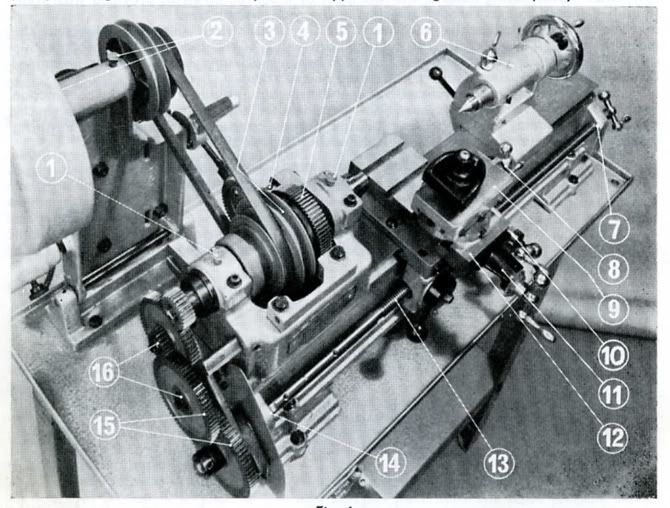
In the meantime here's an overview of the lathe assembly to give you an idea of the layout:
As regards disassembly, here's how I do it.
1. Remove countershaft pulley and changewheel guard covers. Each of these is simply held by a single knurled thumbscrew.
2. Remove electrical switchgear/wiring from its mounting points on bench/stand and lay it aside (main wire remains connected to motor). Remove motor from motor/countershaft assembly. Thus motor/wiring/switchgear forms one block for transport.
3. Remove tailstock by releasing locking lever and sliding it off the bed.
4. Remove headstock belt/pulley/backgear cover. Pull back the cover and this will expose the two boltheads securing it on top of the nearside headstock (clearly visible in the photo). Undo these and remove the whole cover assembly.
5. The ML10 bed slide is formed of a single broad male dovetail. The headstock casting is machined with a single-sided female dovetail seating at the nearside and this mates with the male nearside bed dovetail. The headstock is locked to the rear bed dovetail face by two lugs that apply pressure via bolts and setscews. Hard to describe but the setup and principle is obvious when you see the arrangement. (Sorry, I don't have a photo).
6. Release tension on the headstock drive belt by pushing the toggle lever backward. If you examine the toggle lever assembly you'll see it's held by an 'L' bend in the lower end which simply hooks into a drilled hole in the headstock. To the right of this hole (towards the tailstock) is the right-hand headstock lug described in section 5. Unbolt this lug completely and store it safely.
7. At this stage all that is holding the headstock and countershaft assemblies together is the toggle assembly and the untensioned V belt. Hold the countershaft assembly to prevent uncontrolled tipping and unhook the V belt. Likewise, unhook the lower toggle assembly from its hole in the headstock by pulling it rightwards. Now the countershaft assembly/toggle assembly can be unbolted from the bench/stand (it's secured by 4 bolts and nutted underneath the bench/stand).
8. Finally, undo the left-hand headstock lug and slide the headstock towards you straight off the bed (the belt remains captive).
9. Then all that remains is to unbolt the bed (plus raising blocks if present) from the bench/stand.
I'd echo bogs's comments about keeping bolts nuts washers safely i.e temporarily scewing them back into their appointed places for transport.
Process probably sounds a bit complicated but it's fairly easy once you've done it. Nowadays I can disassemble the lathe for overhaul in about half an hour. The weightiest item is the bed maybe 70-80lbs. (Incidentally, I picked up the 'long', Speed 10 version of the bed last year and humped it from Salisbury to London via passenger rail and Underground on a trolley. I'm 64 and not especially robust so this little lathe shouldn't give you any trouble).
Re-assembly is mostly a reversal of the forgoing but points to note are:
(a) When fitting headstock to bed make sure the respective dovetail seatings are scrupulously clean precise axial alignment of the machine depends on this.
(b) Take care that pulley alignments are correct using a straightedge.
Joe


