Finally, some more progress

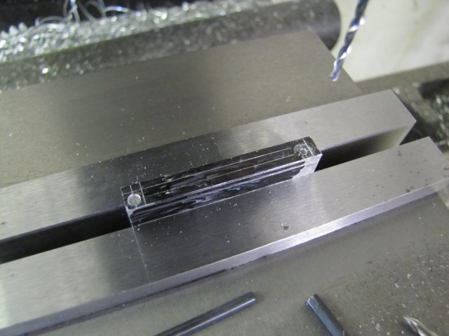
I clamped the cylinder lightly (to prevent distorting it) in the mill vise on top of one of my crude parallels. Some cardboard serves to both protect and to ensure a better grip. Then I used the height gauge to find the top, made a note of the reading, and marked out a line to depth for milling away the port face:
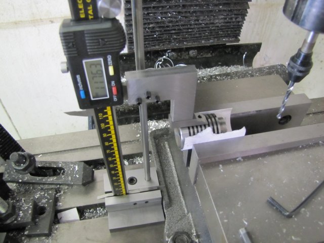
Of course, I first cleaned the mill table well of any swarf in the area where the base was located before doing this!
Then I milled away the port face. As the cylinder was clamped lightly, I milled away the face in small increments; 0.5mm max depth of cut a t a time:
All the passes were done in line with the cylinder bore to prevent it trying to rotate in the vise. When I got close to the scribed line, I checked again with the height gauge, and fed in the last required amount using the Z handwheel scale. As this pass was very light, I opted to do the last cuts perpendicular to the cylinder bore, as it would make it easier to remove the tooling marks later. As a final step, I also milled the clearance flat for the valve pushrod.
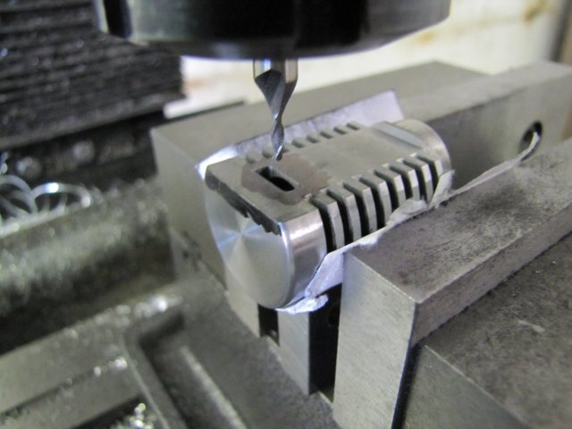
I very lightly marked out the location and size for the valve port with the cylinder still clamped:
Very lightly, as I didn't want deep scratches to have to remove later on!
I went to my engineering suppliers this morning, and returned with a couple of new bandsaw blades and some milling bits, and while there something kept tugging at my mind and wouldn't quite surface. At this point it did

- I needed a 3mm milling cutter for the valve port, and I didn't buy it... 4, 6, and 8 mm, but no 3mm

By then the shop was closed as well

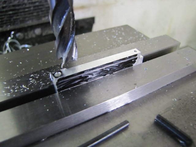
- So I settled on using the 2mm cutter I have, and milled the port - widening it to 3.2mm with a couple of edge passes:
While milling the port another thing raised its head... I'm a pretty easy going person, but one thing I HATE is squeaks. And the mill's y-travel handle had started to squeak - deep in the inside

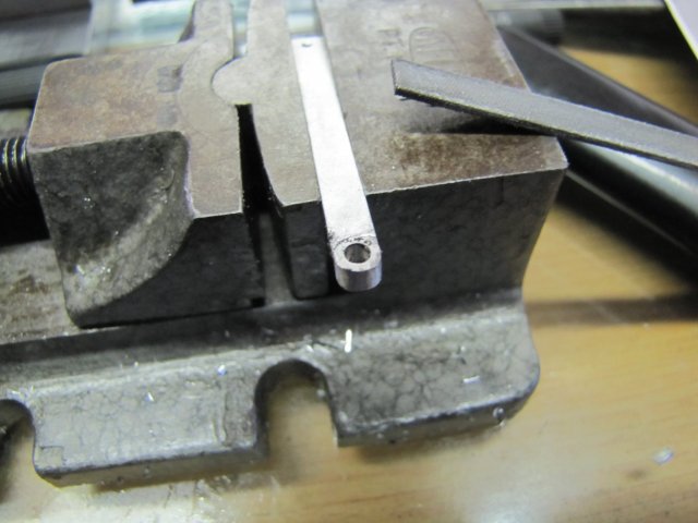
. I removed it, and tried getting some oil in there, but it just wouldn't go down and stop the squeak, so, on to the lathe, and drilled a hole into it from the other end:
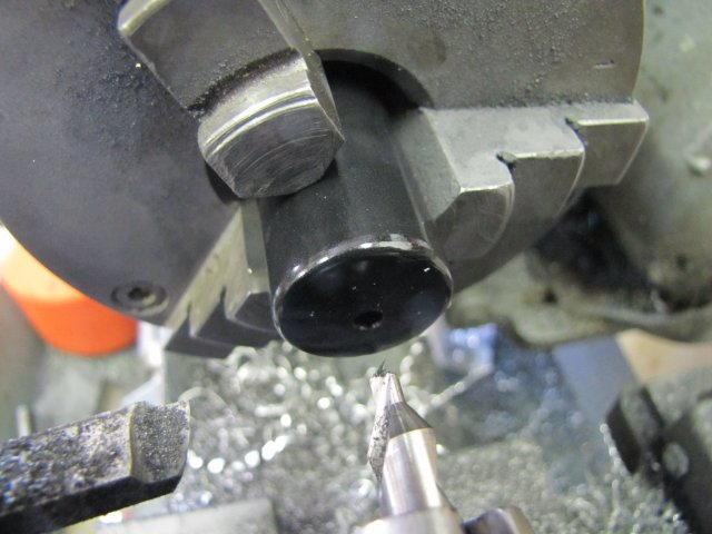
A drop of oil in there, and squeak sorted

It's a pretty crappy plastic handle, so I just might make a nicer metal one in future.
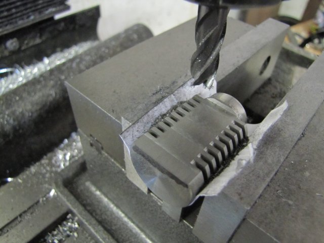
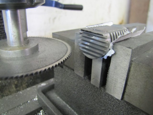
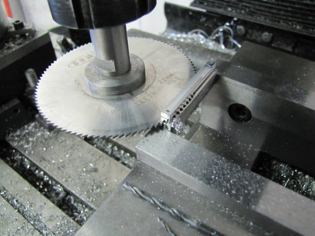
Back to the build... I have the princely sum-total of 2 slitting saw blades; one 1mm thick, the other 0.5mm thick, and fortunately both of the same diameter.
Ganged together on the slitting saw arbor, I could slit the head fins with a 1.5mm gap instead of the 1.6mm called for in the plans. Phil's plans actually calls for slightly thinner fins on the head than on the body, so this is fine; except that I made a slight miscalculation, and instead of keeping the original spacing called for and making the fins slightly thicker, I decreased the spacing to keep the fins to dimensions... Silly me; that left the bottom fin a bit on the thickish side

:
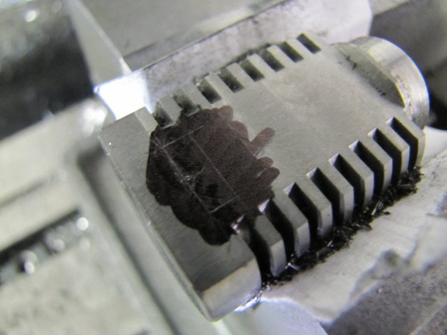
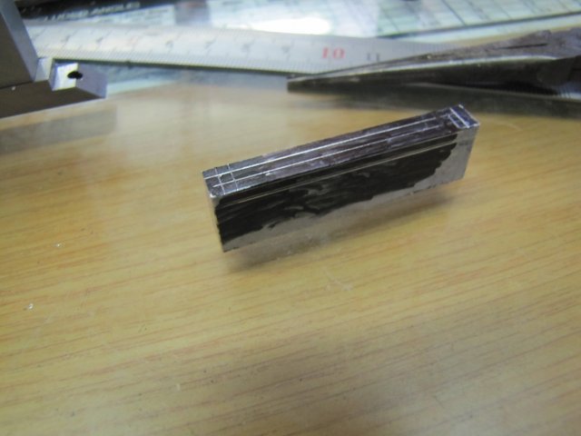
Next I removed the cylinder from the mill, and flat-lapped the port face using different grades of emery on my glass "surface plate" to get rid of the tooling marks, making very sure that I kept it very flat. It wasn't a lot of work; just a few strokes each on 320, 600, 800 and finally 1200 emery, and ended up with this:
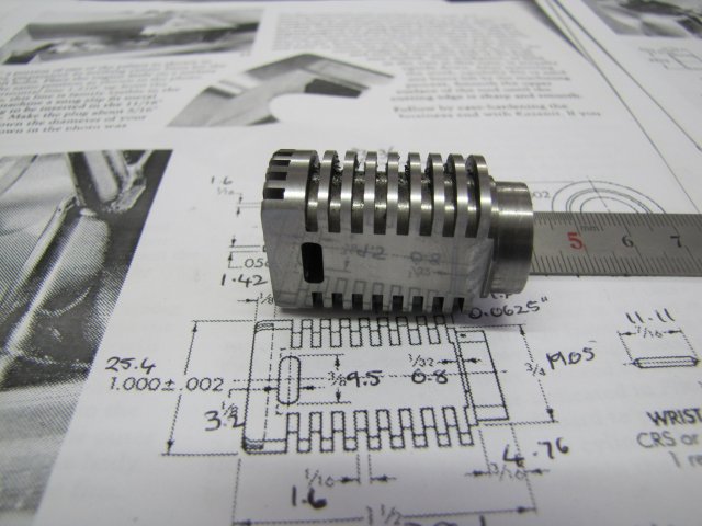
This is one of the nicest surface finishes I've ever gotten on cast iron; and now I know it is possible to get CI to a near-mirror finish!
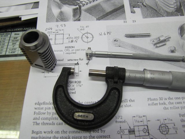
On to the piston, and for this, I brought out the best in my minimalist arsenal of tools; my prized Moore & Wright micrometer and Mitutoyo telescopic gauges. My one sister gave me the M&W many years ago as a gift, and I have never used it much. The set of telescopic gauges I bought last year in a "Cash Converters" shop for the then equivalent of US$10. And they are not fakes... Once in a while one gets VERY lucky ;D. I'm digressing

I set the telescopic gauge to the cylinder bore, and used the micrometer to check the reading; three times over to make sure I had no errors, and then another couple of times just to be 100% sure. I did pick up a slight tightness mid-way along the cylinder bore using the gauge; that's a problem to sort out later:
On to making the piston; I turned the piece of phosphor bronze I have for it down to just over size on the OD, and then drilled and bored the ID to the required size:
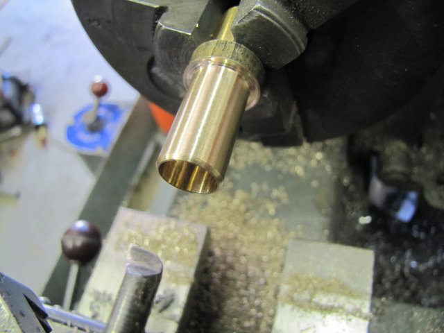
Then I finished off the OD of the piston to 0.005 mm (that's a quarter 'thou give-or-take) smaller than the bore of the cylinder as measured earlier - using the micrometer to check. I have gotten into the habit of working accurate to 0.01mm on my lathe; this was really pushing the envelope for me, so I used my HSS cutting bit as sharp as I have ever been able to hone it, and I was careful to keep a consistent feed while doing the cutting. I used the compound slide set over to 30 degrees to dial in the final cuts; there's quite a bit of reading material on using this method available. Then I parted off the piston; the threaded rod in the tailstock chuck is just to keep it from ending up in the swarf heap:

I'd done well up to now, but forgot one of the most important things I'd learned while making and then parting off pistons
- The parting off raises the metal next to the parting area

- and I didn't pause to clean that up while parting, or even better, do a partial parting before turning the piston to size.
Fortunately I did leave the piston slightly over-size, and would need a mandrel to finish it off together with the cylinder bore. I left the "left-over" phosphor bronze I used for the piston in the 3-jaw chuck and removed the chuck from the lathe; if needed be I could make another piston from that. Then I mounted the collet chuck, shoved a bit of 12mm aluminium in it, and turned it down to a light slip-fit for the bore of the piston. I then used a center drill on the end of it, to allow clearance for the revolving center, and slided the piston over the aluminium, and used the center to nip it up in place. Then I used a rule with emery to get rid of the high spot on the parted-off side of the piston:
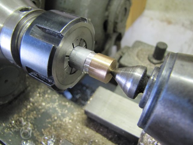
Next I removed the piston, drilled for and tapped an M2 thread into the aluminium arbor, and screwed down the piston on it:
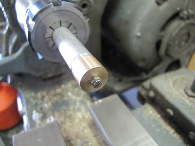
I mixed a couple of drops of thin oil (3-in-one) and some metal polish ("Brasso"), covered the lathe ways with absorbent paper, and coated both the piston and cylinder bore with this mixture.
PLEASE DO USE GOOD SENSE IF YOU TRY TO DO WHAT I DESCRIBE IN THE FOLLOWING SEQUENCES - note I say "good sense" and not "common sense" - last of which is unfortunately worthless nowadays IMHO. With the lathe running at a low speed (on my Myford I chose back-gear medium speed), I started lapping the cylinder onto the piston using the oil-and-polish mixture - with the cylinder lightly gripped in my right hand and moving it up and down the piston, and my left hand on the lathe clutch to stop the lathe if something went wrong. Don't try to use just metal polish; it dries out and will tighten up; the oil added to the mixture helps to lubricate it. And if things tighten up, release your grip on the cylinder first, and then stop the lathe.
There was not a lot of lapping required, but the tight spot I mentioned earlier in the post while measuring the cylinder was still there (easily felt by a tightness requiring a bit more holding torque when moving the cylinder over that point), so I chose a quick-and-dirty fix for that.
A proper lap would be the best way to go, but I sawed a slot on the mandrel to hold some folded up 800 grit emery trimmed to size to lightly fit the bore of the cylinder when wrapped around the arbor.:
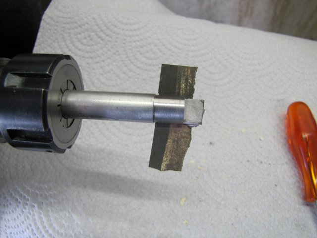
I shoved the cylinder over that, moved it over to where I'd judged the tight spot to be, and started the lathe, once again holding on to the cylinder with my right hand and moving it side-to-side a little bit. Just a couple of rotations of the lathe to run that tight section in a bit, and I was done with the more dangerous stuff. A video to break the monotony, and show how the piston fits the cylinder:
OK - End of risky sequences Next I started on the wrist-pin bracket. This one called for aluminium as well - I'd originally set out brass for it, but with the weight of moving parts on this engine playing a major role, I changed my mind and used aluminium. I have some 5mm aluminium rod scavenged from old UHF TV antennas, but that is horrible stuff to machine, as it is extruded soft ali. As I have been extravagant on wasting aluminium on this build thus far, some more wouldn't matter anyway, so I flipped the bit of 12mm I already had in the collet chuck from doing the piston to get at the un-machined end, and turned it down:
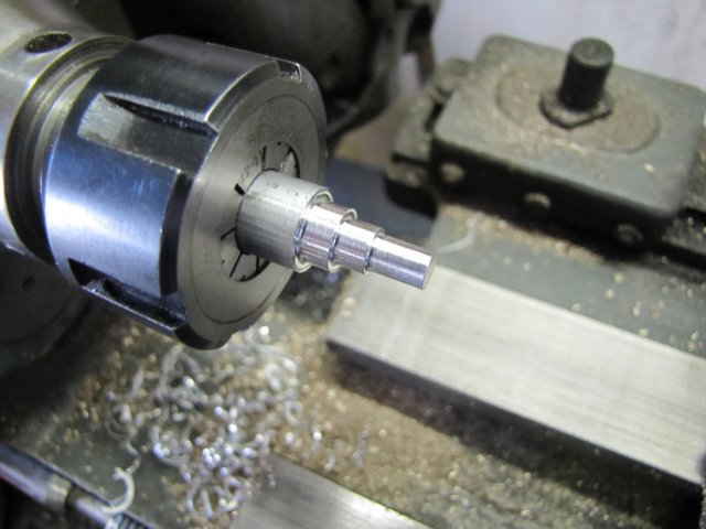
I just used the step-turning to prevent flexing; though the whole lot could have been done in one go. The tip is down to the correct size, with some room for machining left on the thicker bit.
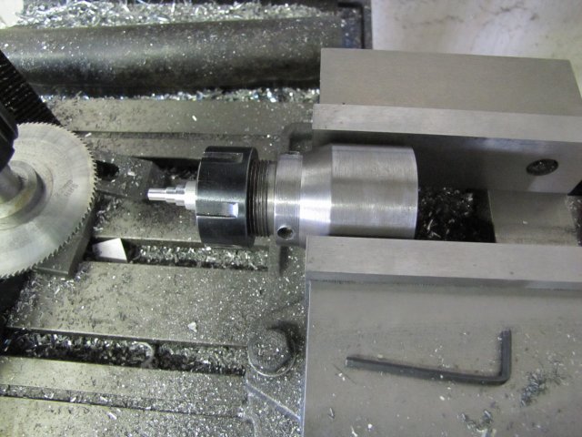
The front bit needed to be slit for the connecting rod - and with some more machining in the lathe to come after that, I took the plunge, and unscrewed the lot - chuck-and-all from the lathe, and lightly clamped the collet chuck in the mill vise. When I built the collet chuck, I left it chunky, so I don't think it will distort from getting used in this rather unconventional way:
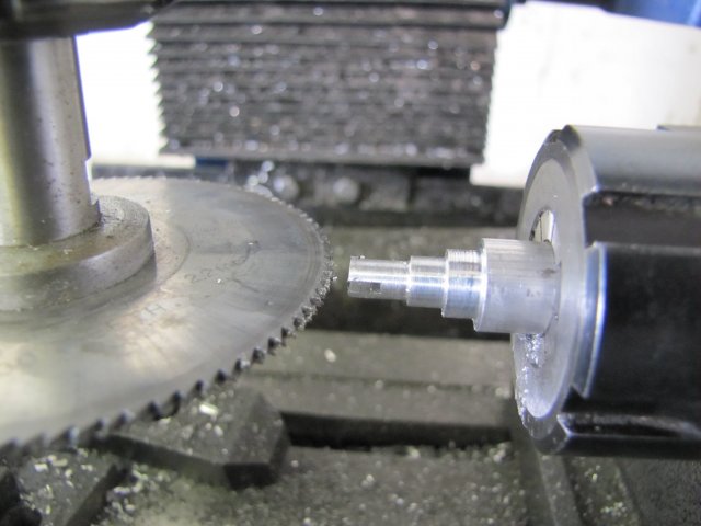
Then I slit the ali for accepting the connecting rod - specs show 1.6mm, but I did it at 1.5mm:
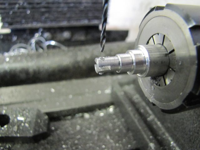
And cross-drilled for the wrist (gudgeon) pin:
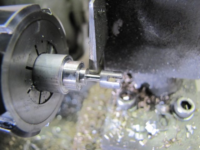
Back on the lathe again, and I just used the rear parting tool to trim the lot down to length, and with a 2mm diameter back end - to get threaded later:
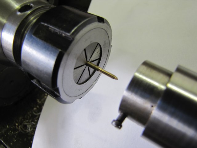
After final parting off, mounting in the collet chuck to thread the shaft M2 with the tailstock die-holder and a bit of clean-up, the wrist pin bracket was done:

I was surprised; this is a fairly small part and it came out OK without any hassles!
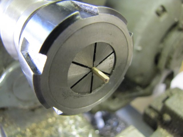
The valve pushrod followed; nothing difficult; just a bit of 2mm bronze brazing rod - threaded M2 at one end:
And with a flat filed free-hand on the other end for a grub screw (set screw):
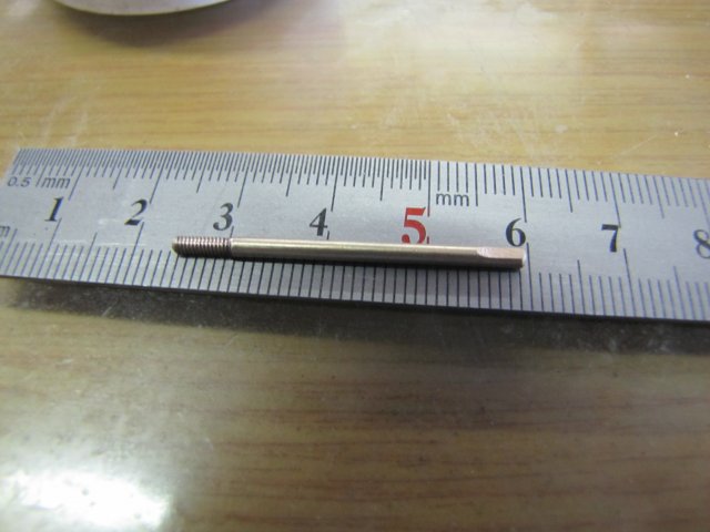
One valve push rod done:
With a bit of time left in the shop, I started on the connecting rod - marked out some ali:
Drilled for the big- and small ends:
And milled to size on the accessible sides:
I used a slitting saw to trim it off the parent stock:
When it started to wiggle around - JUST before it was fully parted off, I stopped the mill, and broke it off by hand. Saves one from having to search for a part tossed across the workshop on final cut-through

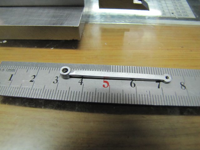
Some filing was required; I could have done more to it on the mill, but setting up sometimes takes more time and energy than a bit of judicious filing:
Connecting rod done; I'm not entirely happy with it as I over-filed some spots (So much for "judicious" filing
) - but it should do for now:
For anybody that reached reading this point in the post, -

Darn, I admire your persistence, as I was starting to bore myself!
In a nutshell, the results of today's efforts:
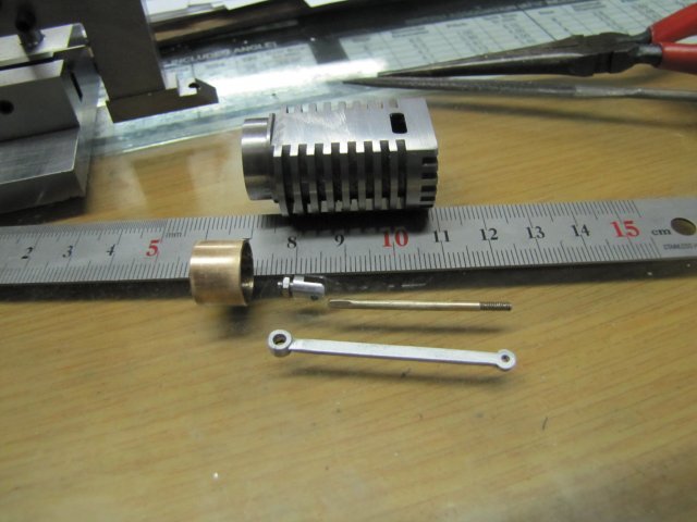
I hope to get a bit more done tomorrow
Regards, Arnold


