One last bit on the

section..... Scott, Don't go to the Renault 5 GT turbo's.... You'll regret it!
Now...... On with the real topic!!
I finally got to spend a few hours in the 'shop yesterday, I got a little busy with re-design and testing, here is what I got upto.....
Warning!!... This post is going to be a monster... With lots of big pic's!!!So, Go with advise received and polish the clamp plate up a bit
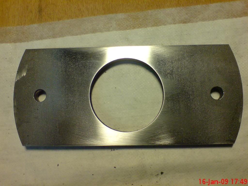
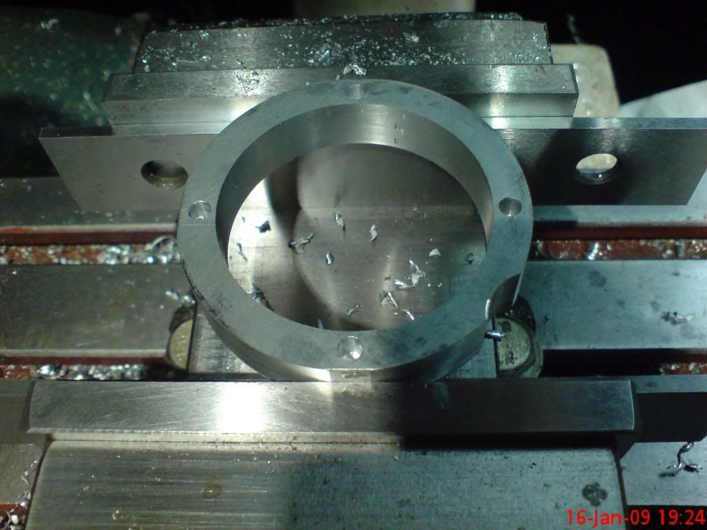
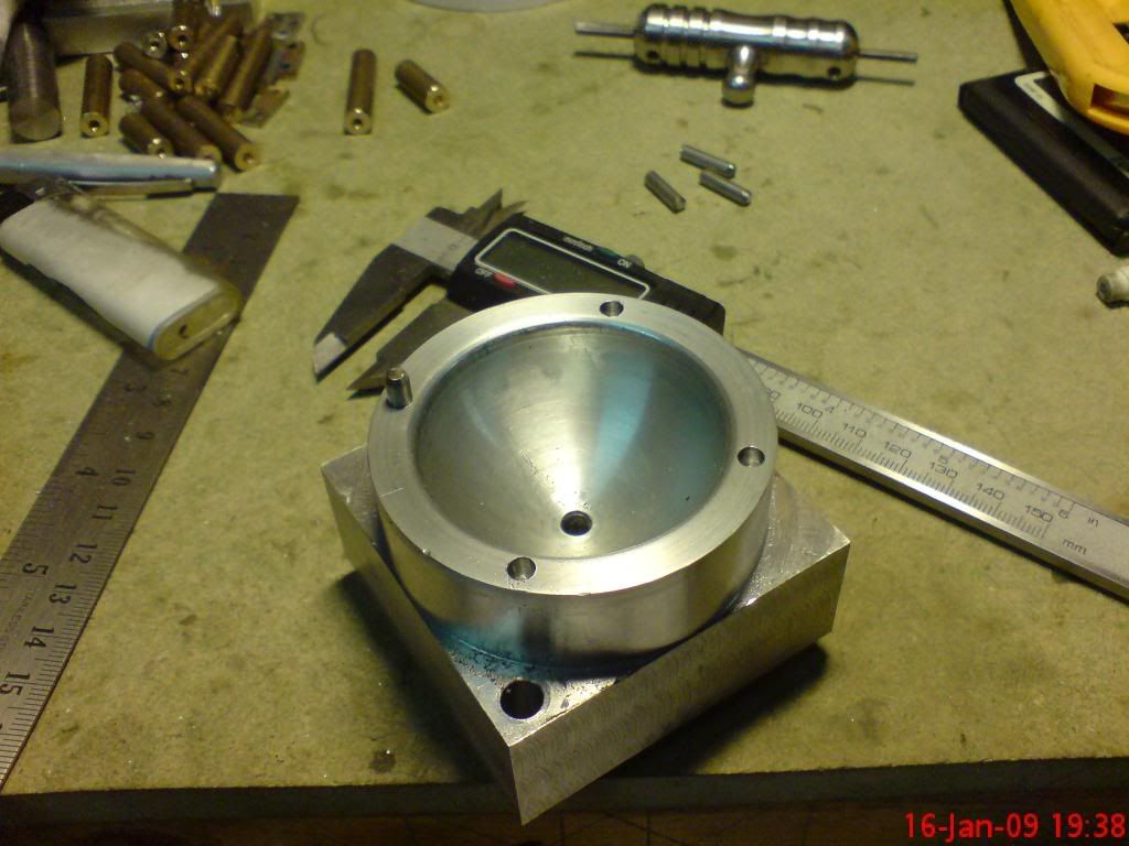
Then make a riser for the die (deepener really but that don't not sound right!?!)
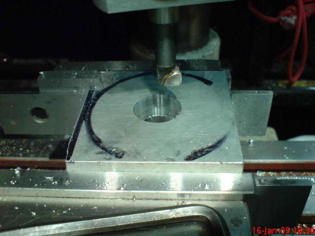
This may not look like much but my boring skills were lacking.... So after a little tutorial from Bog's when I saw him last I had a go.... Worked well John

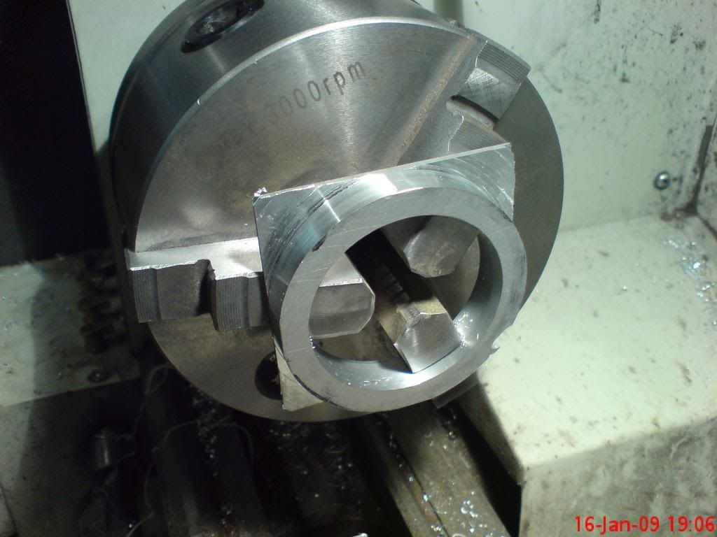
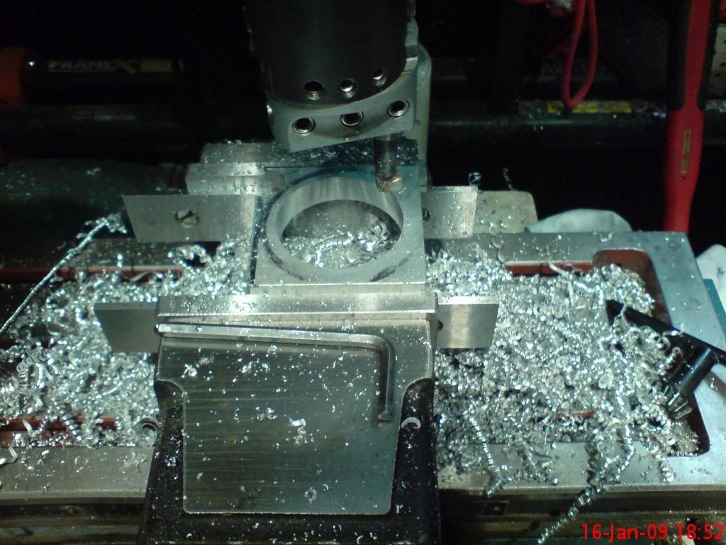
Once the part was the right ecternal for the die it was drilled for 4 dowels as was the die.
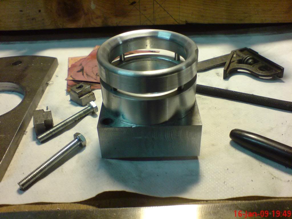
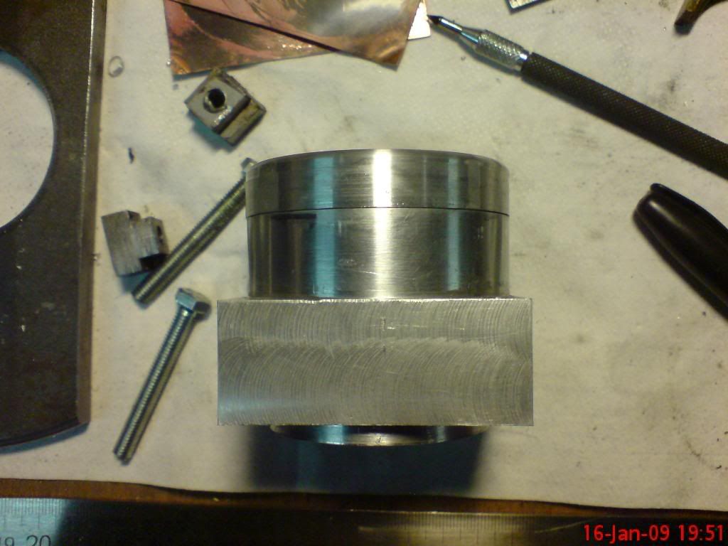
The top edge was bevelled to try to avoid the grabbing experienced in earlier attempts. Then the two parts were pressed together.
Now the bit I've been waiting for.... Test! I purchased some copper sheet 6x3" in 3 different thicknesses 0.9, 0.7 and 0.5mm. I thought I'd stary with the thinnest one first, so I sheered a 3x3" square off and drilled the 4mm hole in the centre for the pin. I then annealed the sheet (noticably more malleable than the brass) and set it up in the press (as per earlier pic's with the springs)
Then a couple of stamps later....
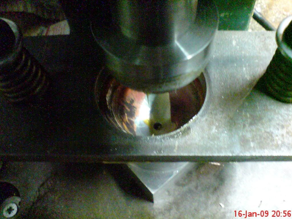
A bloody big split!!!
Not to be disheartened I tried the 0.7mm sheet. This also started to split, at the hole! So the next logical step... No hole!
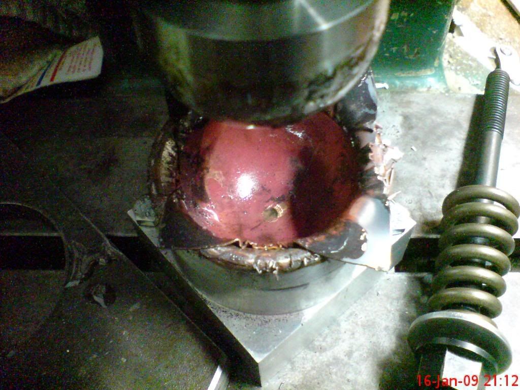
I removed the locating pin from the punch and tried another 0.5mm sheet. This time with no hole in it and lined up by eye, also after the last two attempts I decided to press this one hot, got it to a cherry red just before clamping it into position.
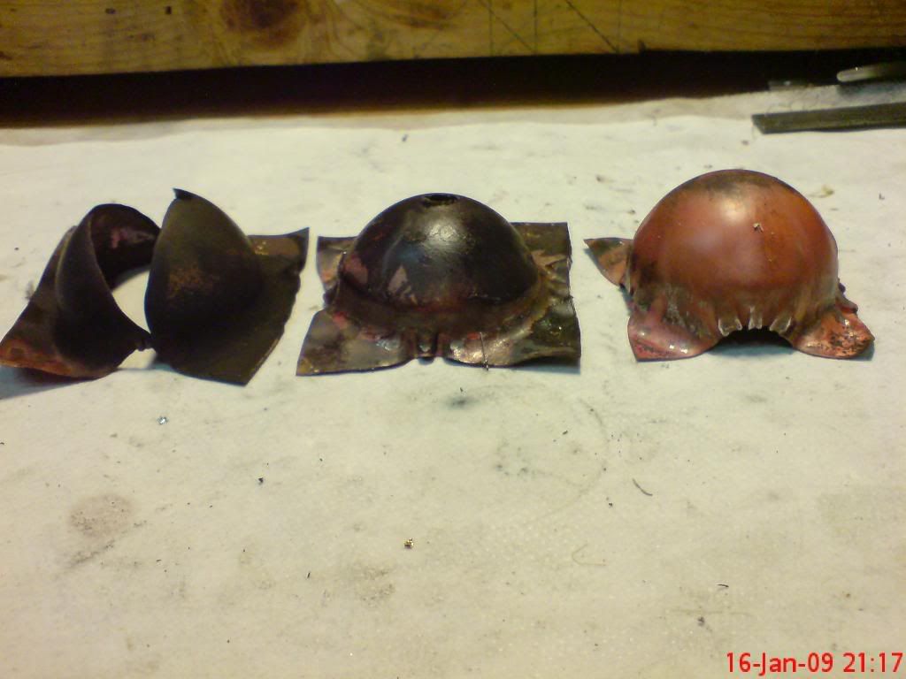
The result...
From left to right, the first attempt split. The second attempt splitting before the form was complete and finally the last attempt. The conclusion I need to start with a 4" square/circle and then press it hot and without a locating pin/hole.
"But wait" he says There's more.... I also had a bit of fun with the prototype shape already created....
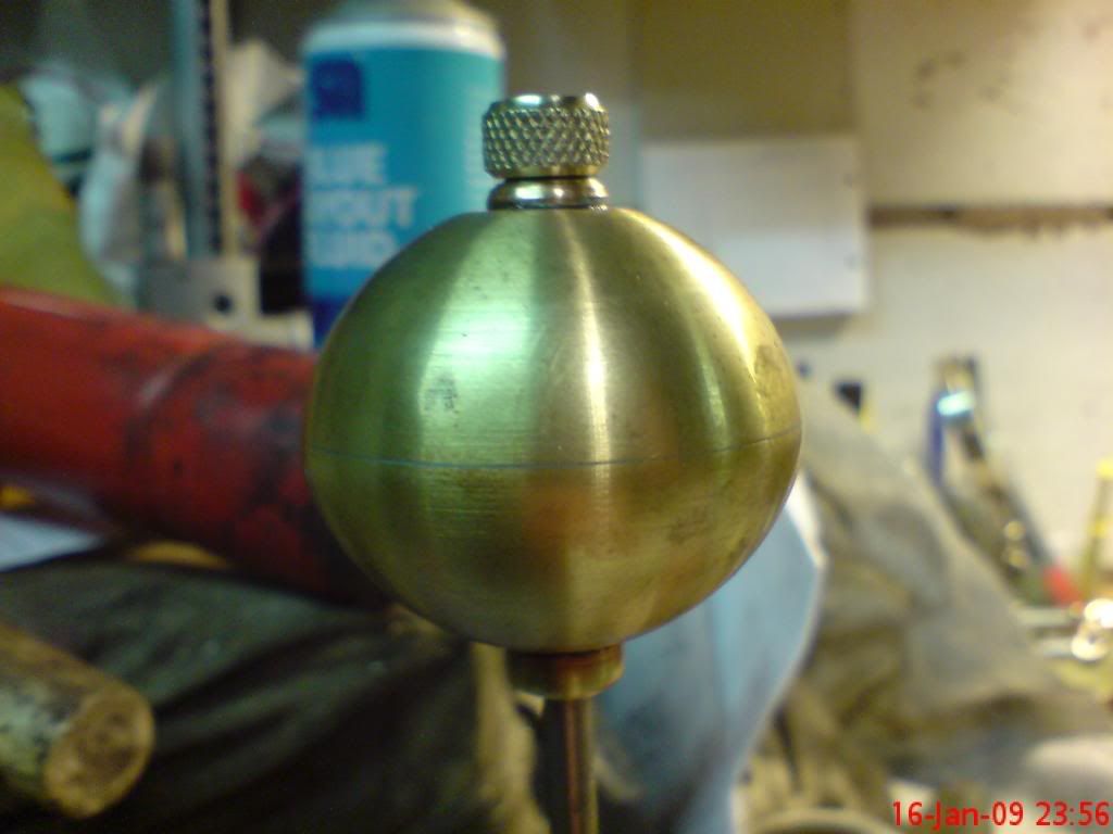
A taper bored central axis was made and then soft soldered into the shape,
An internally threaded part was also soldered into the opposite hole for a filler plug to be screwed into (localised heat used to save de-soldering the shape at it's seam.)
Then on a tangent (whilst waiting for the shape to cool down) I made a little mod to the punch head, A small brass rod was friction fitted into the hole left by the pin. This was then shaped into a very shallow dome with a hole in it's centre. The theory, it will hold the form in the centre whilst punching is being performed and might give a little relief for the drilling that will have to be performed after pressing now that the hole is not being drilled first.
Quick test in the better of the already pressed test forms...
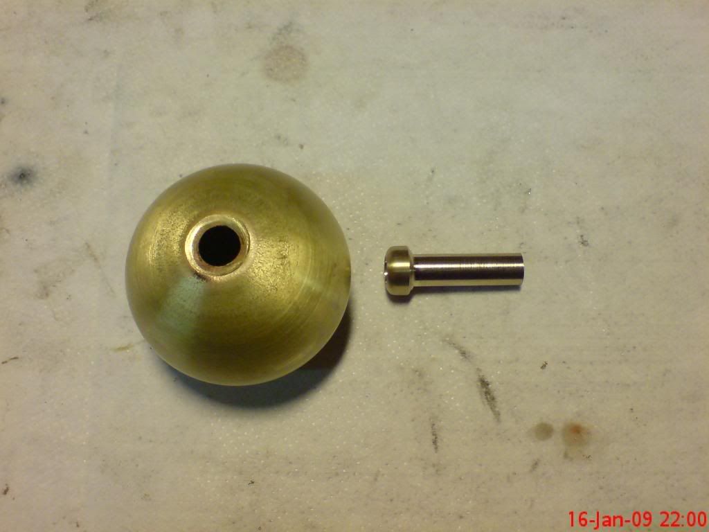
Then onto the soon to be figured out jets.... After a discussion with Bog's a few months back, a small plan was devised to narrow the end of a small dia brass tube.
This is that plan, well my version of it anyway!
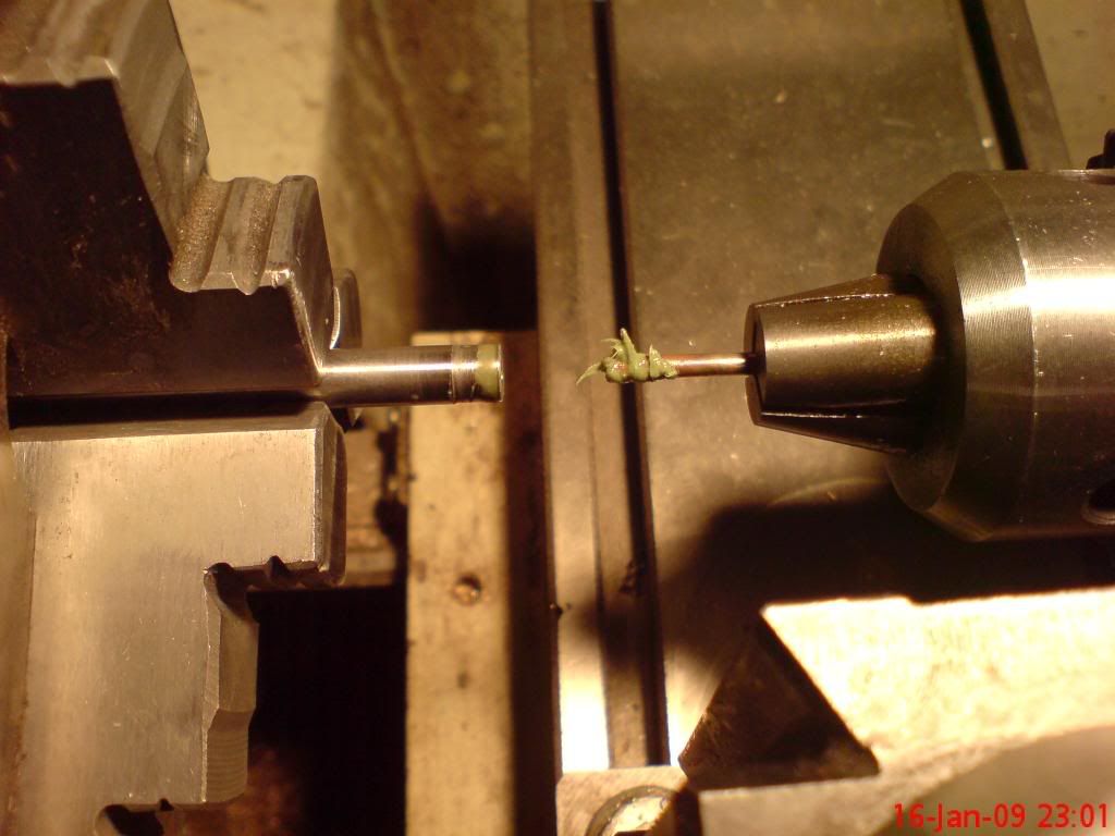
A hole drilled into a stainless rod was then reamed (in a fasion) out with a carbide tapered cutter. The use of plenty of trefolex helped this process (the first attept burned the teeth off the cutter!!) I used the whole tail stock to slide back and forth, use of the cutter like a drill will burn the teeth off it, it needs to be a push and retract action in quite quick succession.
A small test section of the tubing was cut and the very tip annealed, this was then held in the drill chuck lubricated and forced into the internal tapered rod. I used the tailstock lock and advanced the tub in using the tailstock screw (like drilling).
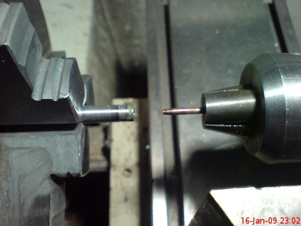
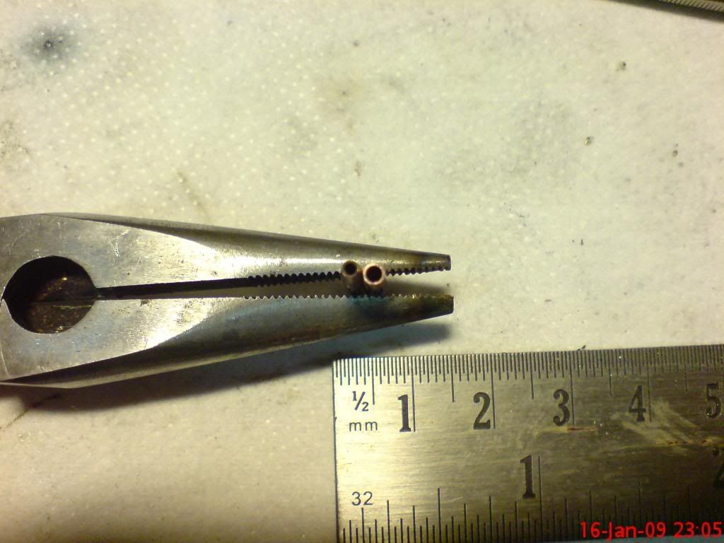
The result... A tapered jet
Then just the addition of the screw in bung with a rubber 'O' ring and that was it for last night.... I'm getting there slowly!!

Ralph.


