Eric wanted us "lurkers" to post, and it's been quite a while since I posted here on MadModder, so I'm obliging

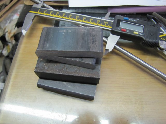
I need a height gauge for my shop, and it's time to build one. A "cheap" Asian digital caliper will do the measuring, but I do not really want to modify the caliper - the "cheap" ones are expensive here in Namibia, so I want it as backup; just in case...
There are a couple of very simple designs around for turning a normal caliper into a height gauge, but I do want a bit more rigidity from the setup, so I'm slightly over-engineering this one

I have a couple of meters of 10x60mm hot-rolled flat bar, so - put some of it to use, together with a short bit of 18x40mm HRS that I found. A bit of 6mm silver steel and some 4mm square HSS completes most of the basic building blocks:
There will be some more material needed to finish the scribing/measuring arm, but I'll add that later when all the dimensions are finalized.
The HRS is pretty horrible stuff to machine, but here goes.
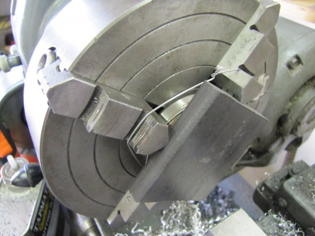
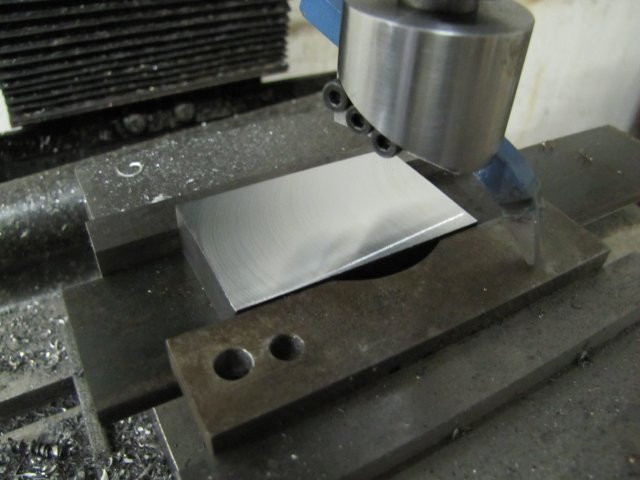
For the base, I set it up in the 4-jaw; just roughly on center. My lathe faces ever so slightly concave, and this makes it ideal to turn up bases for things that need to stand flat. A bearing shell is used as a parallel to get the workpiece out from the chuck a bit but flat to the chuck face. A light tap with a hammer on the workpiece while tightening up the chuck jaws makes the bearing shelll sit pretty tight. As the bearing shell cannot be taken out between the jaws it is perfectly safe to use it like this while turning. I do tie it down with some binding wire to the chuck jaws though, as I do not want it to start tumbling around and marring the chuck face should it come loose while turning:
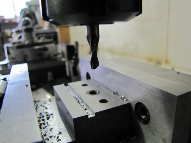
Next the scale needed to get cleaned off the bits... On to the mill - similar sized bit sticking out from the vise on a bit of a makeshift parallel setup:
And some flycutting later:
The scale really takes a toll on my HSS flycutter, and I got tired re-sharpening it, so I decided to do an experiment. I bought a couple of carbide tipped tools a while ago; one left and one right-hand. On my lathe I'm not too happy with the results - so If I stuff up one of these it's not really a waste. I mounted the right-hand bit in the flycutter; it has an 8mm shank just like my HSS bit I use, so no fussing around needed. Then I played a bit with feeds & speeds; it turns out the cutter wants my mill's top speed (1200RPM) and a good rate of feed - about 3mm/second

- this is the result:
I was scared of the carbide tip chipping from the interrupted cuts, but it just chewed through all the gunk. And taking 0.5mm depth at a time at the speed above. The finish is not quite as good as I get with my HSS cutter, but quite satisfactory - and MUCH faster

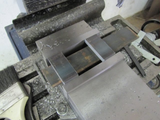
Next all the cleaned up bits was clamped together on the mill bed - to the best accuracy of eyeball MK1 - with the areas I wanted to drill and ream directly above a T-slot for clearance - then a couple of holes drilled at 5mm with the outer two further enlarged and reamed to 6mm:
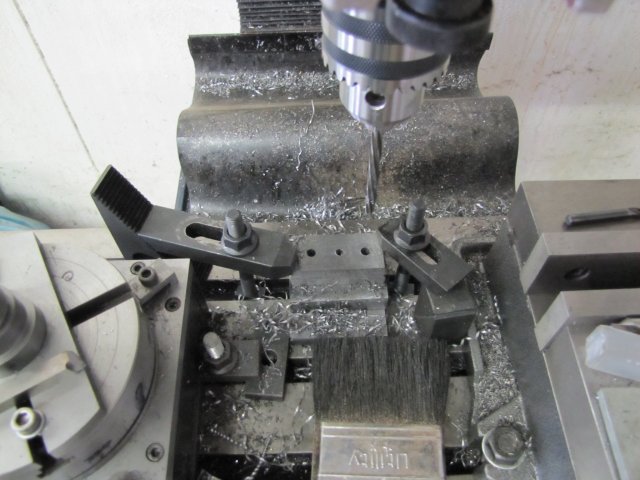
The middle 5mm hole in the base plate was threaded M6; I'm right-handed, so normally start a hole with my right hand, then finish threading with my left hand, as I tend to have better feeling of what the tap is doing. I keep my arm in-line with the tap and use my wrist to turn "on the center line", usually just with my forefinger and thumb to twist the tap wrench. In the next photo my arm is not in line... - it's a bit awkward to do that and handle the camera, and I've never been known for having a rubber body

:
This is the method I have used on hundreds of holes for tapping from M3 upwards, and have not yet broken a tap in these sizes, so it does seem to work. The one and only tap I've broken so far is an M2 last year; in some work-hardened stainless - and for M2 I use a tapping guide.
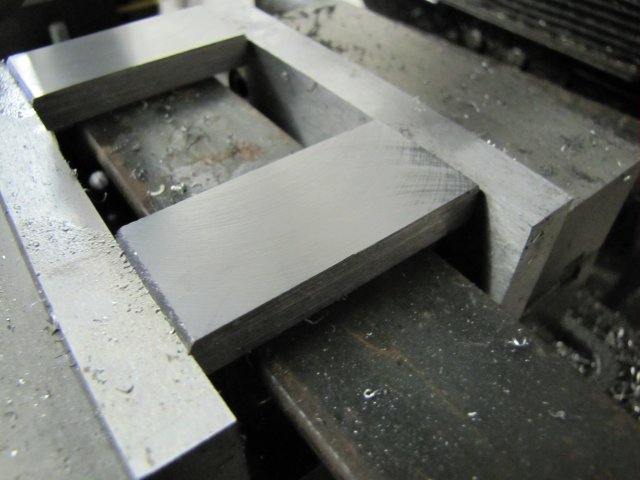
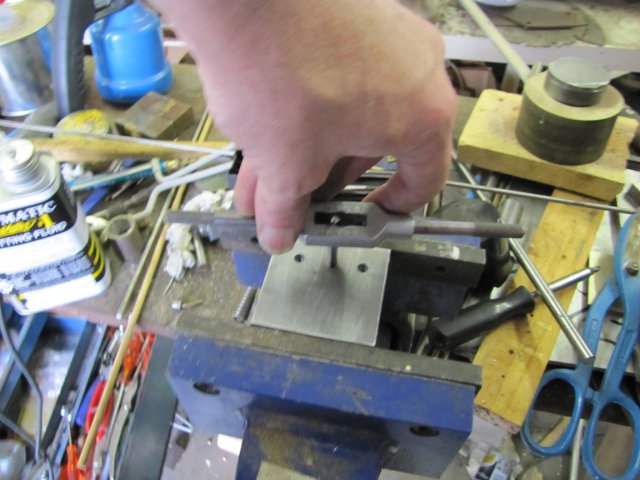
The thicker (18x40) block was counter bored and drilled out to take an M6 cap screw; I thought I had a photo of that, but don't... This was screwed to the base plate, and a 6mm drill and a bit of 6mm silver steel (my collet chuck's one locking lever actually) used to align things through the holes, and then all was clamped together in the mill vise for some more cleanup with the flycutter:
Not a great finish - but at least my mill's tramming is spot on....
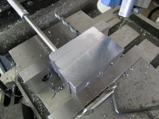
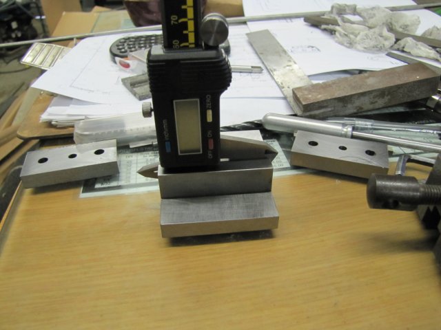
The 18x40 block needed a slot milled in it where the caliper will sit. I measured the calipers I have and their thicknesses range from 2.8 to 3.5mm - for identical-looking calipers. So I decided to mill the slot at 4mm wide - anyway, my smaller milling bits can't go deep enough. I may not break many taps, but milling bits are another matter

:
Fortunately I had one spare 4mm milling cutter to finish the job.
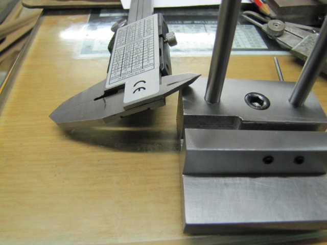
Still some work required, but this is how the caliper will sit in the slot:
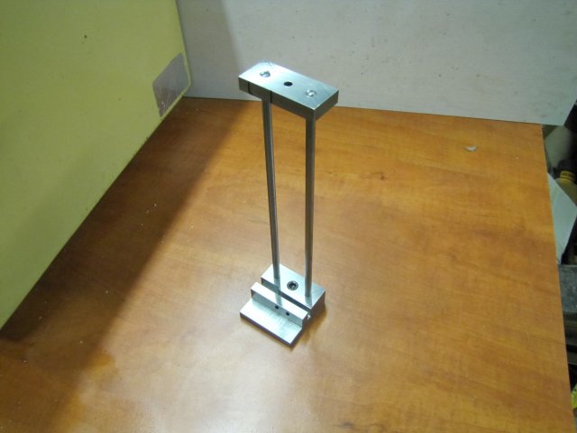
Some more drilling and tapping for set screws on the base later, and this is the end result so far:
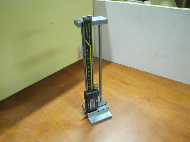
With the caliper installed:
It still needs the scribing/measuring arm and a retainer for the caliper arm to the top section.
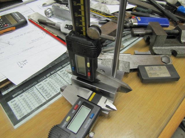
I ended up milling a step in the mounting slot so that the caliper's slide can go down right to the bottom; this will make the measuring arm a lot shorter. This photo shows the end of the caliper and the extra milled space in the slot:
Without any changes except for the upright lengths, the stand will actually take my bigger 200mm caliper as well:
I'd hoped to finish this this weekend; maybe I'll get a chance during the week...
Regards, Arnold


