Hi Guys
I promised in my introduction (Another Aussie) that I would post some pictures of my workshop
Below is a quick video to give you an idea of the layout.
http://picasaweb.google.com.au/lh/photo/8TbZBdwq_ksVE-qUSqnkpreIHfZkj7-BBaMiKMjRjew?feat=directlink It is not a big shop at only 3.3m x 3m but big enough to have fun. I keep it tidy as it makes doing and finding things easier. You may have guessed I have not long finished the shop as there is still plenty of wall space to fill with shelves and hanging items.
Now some pictures of the machines
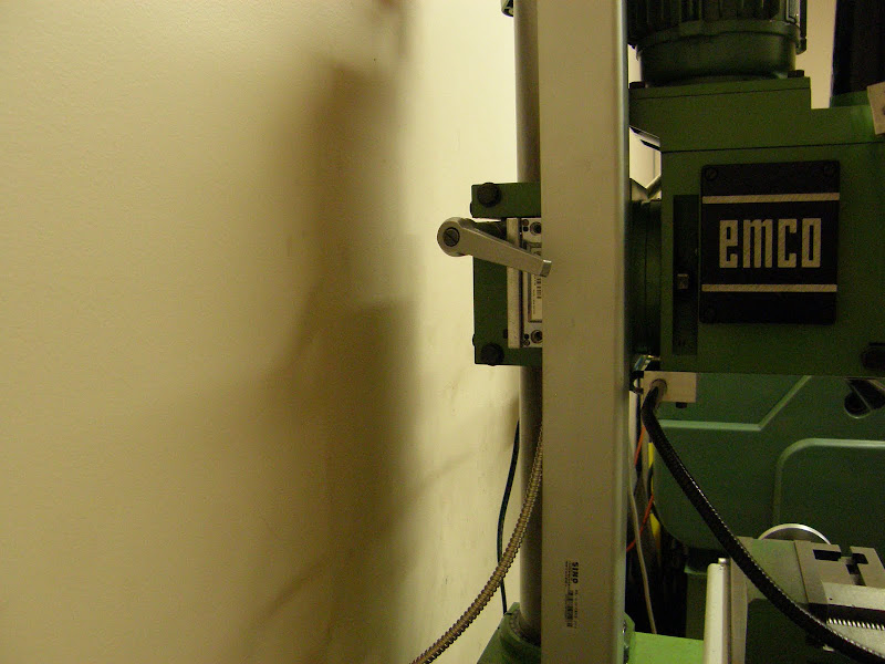
The mill is an Emco FB1 (made in Austria). It has a 6 speed (120-200rpm) geared head and a 3 speed drive for the X axis.
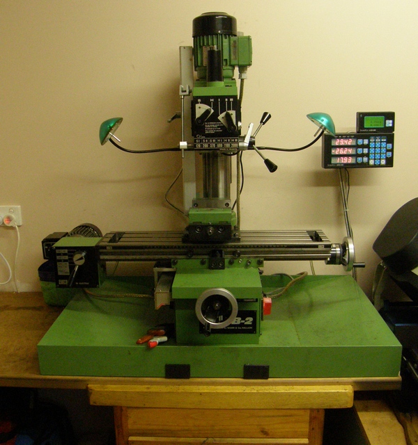
I added the two lamps which started life as desk lamps. I put a 12V halogen light transformer in the base of the mill with the rest of the electrics and a splash proof switch adjacent to the motor switch (red knob on the base).
The mill came with a large angle plate and I spoilt myself and bought a 6in Vertex rotary table. I found a supplier in Hong Kong (CTC Tools) that has good quality tooling at very reasonable prices so I also bought 2MT ER32 collet chuck to fit the rotary table.
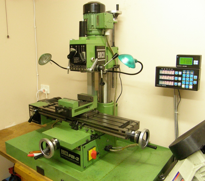
I recently fitted a Shumatech 550 DRO (was lucky enough to get into the power buy) and have fitted glass scales to all three axis. The Z axis is fitted to the column/head as the quill only has 40mm travel and I only use it for drilling.
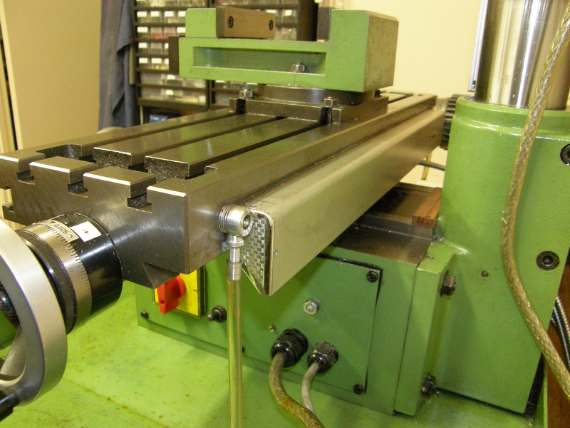
X axis scale
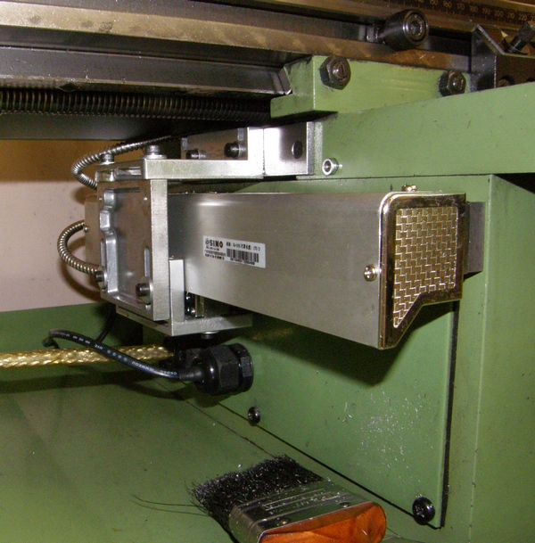
Y axis scale
Z axis (sorry not a good shot)
The bandsaw is one of the many 4 x6 clones. The machine with the supplied legs was too low so I mounted it on a set of second hand drawers that I fitted with casters. This raised it by around 150mm which is a much more comfortable height. I pull the saw out to use, when using the mill (clearance for the right end of the table) or if I need to open the lathe change gear cover.
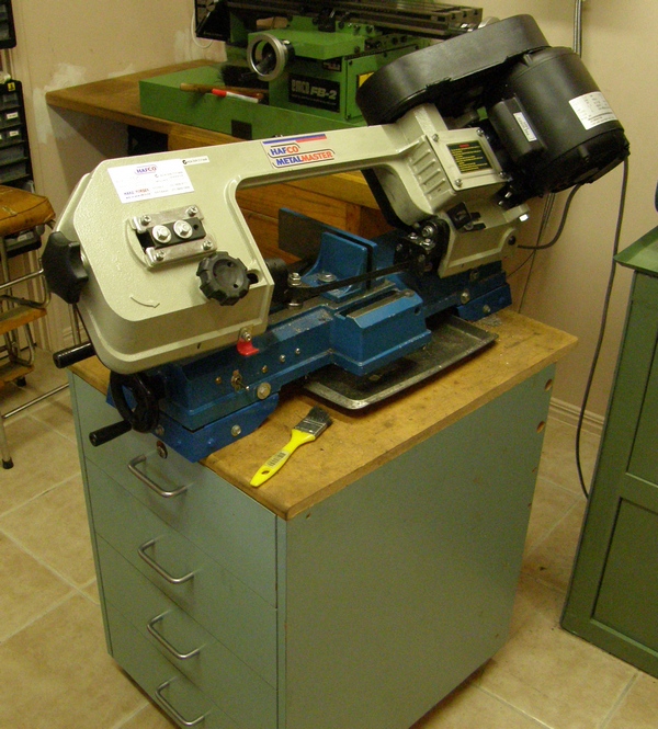
Still need to make some mods to the saw such as replacing the vice bolts with extended handles, T nut for the fixed jaws angle adjustment, extended moving jaw etc.
My Lathe is an Australian made clone of a Boxford. It has a 1 ¾ in, 8TPI, 4MT spindle nose and will pass 1 1/16 in. through the bore.
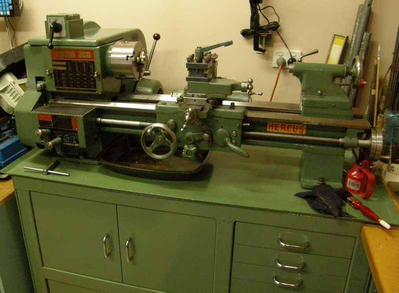
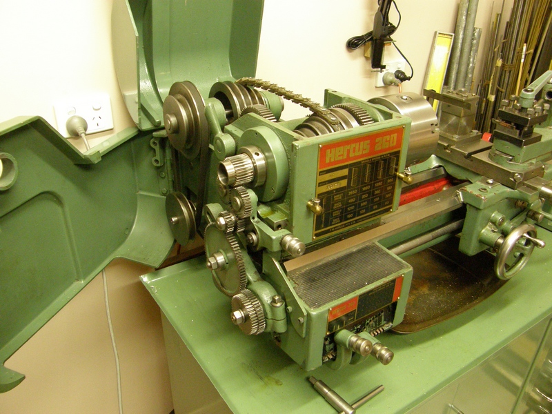
The lathe has 16 speeds (8 direct, 8 back gear) covering 65 to 2650 rpm and a screw cutting gearbox with 8 tpi lead screw. It came with the stand made from 2in sq tube. I made the drawers, lined the frame and fitted the cupboard doors as you cant have too much storage.
I have a good range of accessories for the lathe (steadies, 4 jaw, ER32 chuck & collets etc) but the next job on the list is a QCTP.
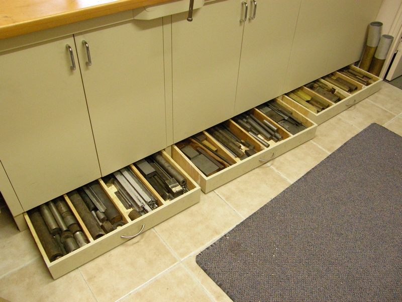
When I built the work benches I put cupboards below as I like the shop to be tidy (or should I say I hate not being able to find things). Built rollout drawers for material storage under the cupboards.
The video shows a small Chinese made drill press that doesnt get used, as it chews belts, a copy of the George Thomas sensitive drill that I will convert to a tapping stand and a normal drill press. I also have an 8 mm Lorch clockmakers lathe with some accessories. I would like to mount this on base with storage drawers underneath but it is a fair way down the list at the moment.
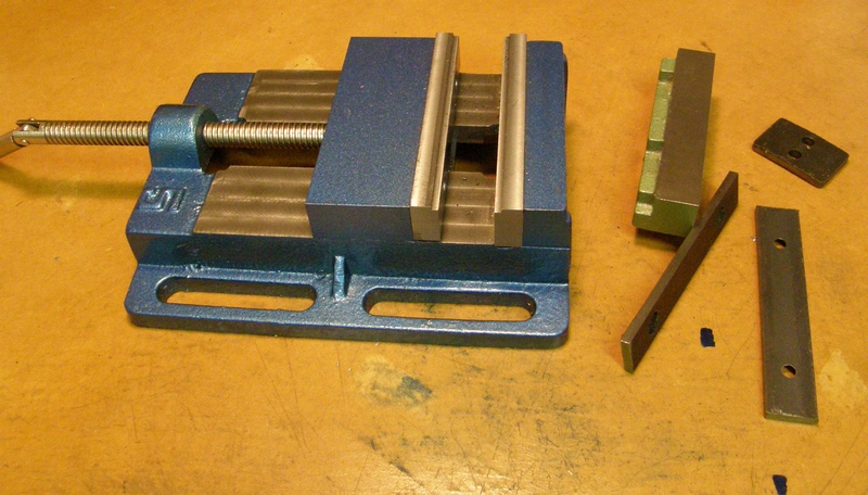
I purchased a cheap 4 in. drill press vice but it had a small moving jaw, bent keep plated and significant jaw lift. Following an article by Harold Hall in Model Engineers Workshop (MEW) I sourced a block of cast iron for a replacement moving jaw, skimmed all over to true up the base, extended the keep plate ways, skimmed the jaw slot & ways and made a new keep plate. Below are a couple of pictures of the rebuild vice showing the old jaw, keep plate and what was fitted as removeable jaws plates. It is hard to make out in the pictures but I have milled a 3 x 2 mm step on each jaw to grip thin material.

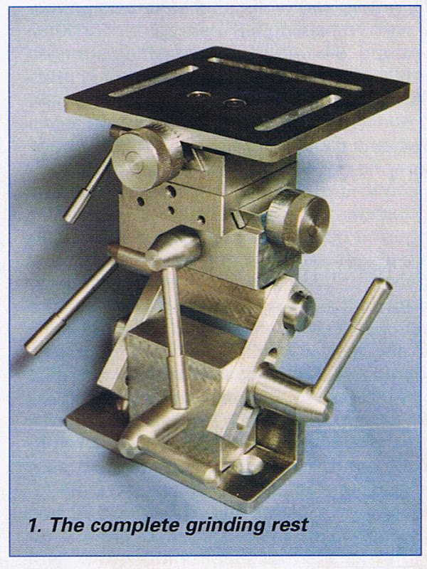
I am currently making a grinding rest designed by Harold Hall (published in MEW). The design includes fixtures for sharping drill bits, end mills, lathe tools and slitting saw blades.
This is what it is meant to look like when finished.
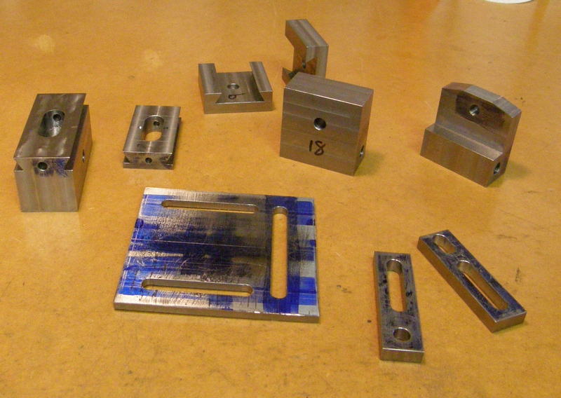
Here are the parts completed to date.
Here is what the End Mill grinding fixture will look like.
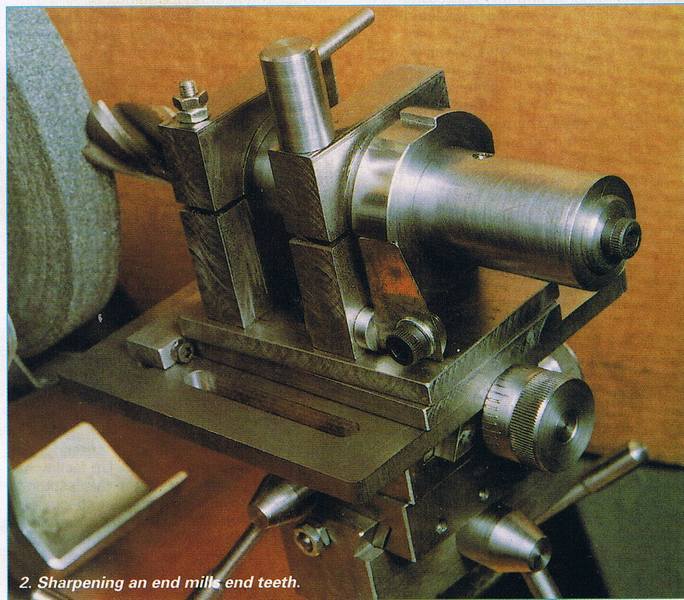
In response to my introduction post John Rudd asked for pictures of the grinding rest so I will start a new topic to track progress with the build and accessories.
Eric (Brass_Machine) asked for details of progress with my clock.
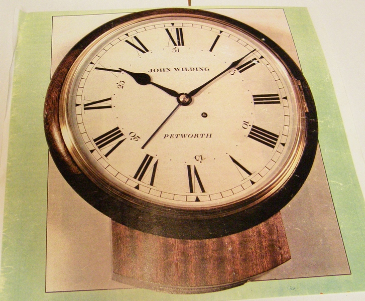
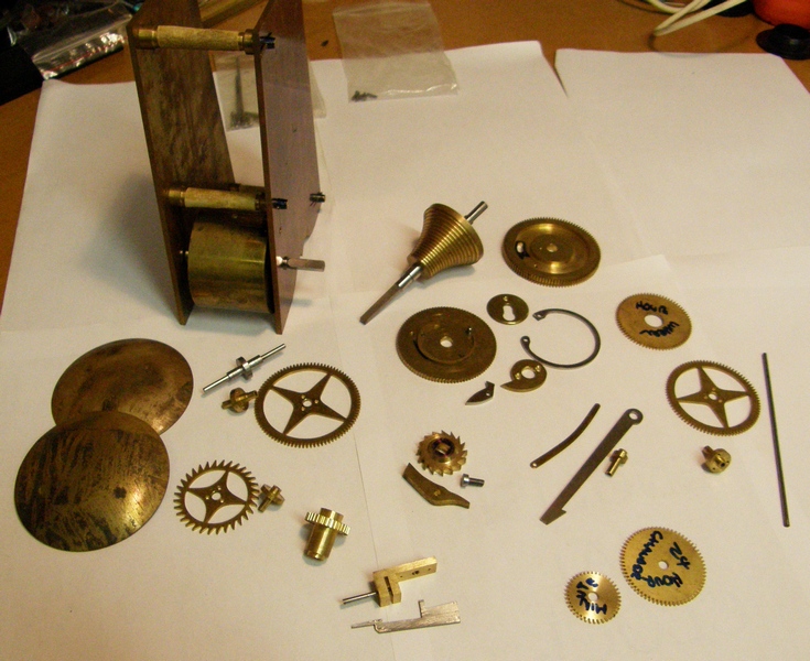
The clock is an 8 day, 12in English dial clock designed by John Wilding and published in Clocks magazine. It is spring driven with fussee and is regulated with a 9in pendulum. I acquired a set of wheel blanks with the teeth already cut and the pendulum bob blanks but have made everything else from scratch. Most parts for the movement have been made with just a couple of collets required for the wheels then comes the planting of the train, getting it to run and finally a complete strip to polish. After that is the dial and case.
Here is what the completed clock should look like.
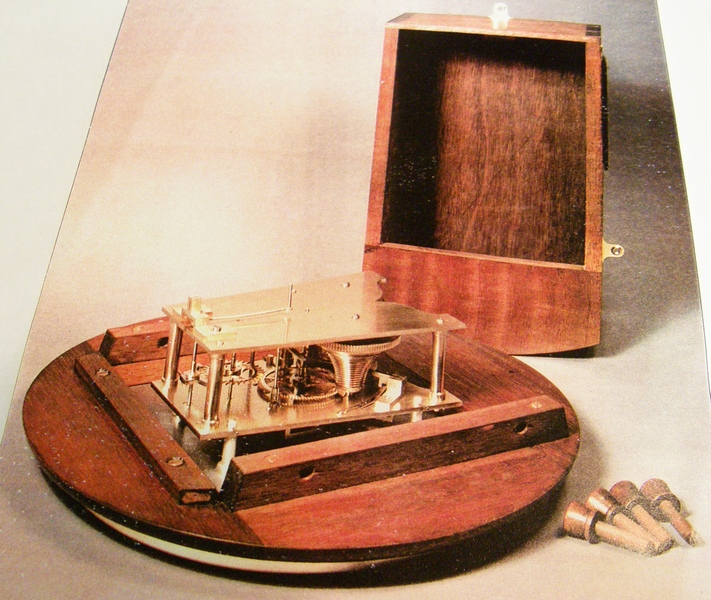
And here are the part made to date.
Again, if anyone is interested, I will start a new topic on the clock once I get the grinding rest and QCTP completed.
Hope this post was not too long and was of interest to the group.
Col


