Yesterday, the job progressed a bit further, but my efforts ended with a bit of a disaster.
I needed to get the flywheel and poly-V pulley (both keyed) off the new motor, and attach the 3-step pulley from the old one. The flywheel came off easily, but the pulley needed persuasion using bolts and the long nuts from a clamping kit as jacks. The 3-step pulley from the old motor was easy to slip off its keyed shaft, but there was no keyway in the pulley itself. It was secured by a grubscrew going into the keyway in the shaft. Im wondering if I should bother cutting a keyway into the pulley. The grubscrew method seems to have lasted 40 years without any problems.
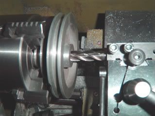
The pulley was held in the 4-jaw and persuaded to run true. I couldnt find either a suitable boring bar or the one I once improvised by grinding up an Allen key, so I used one of the good teeth left on a damaged ½ endmill to enlarge the bore from 5/8 to 16mm.
Next: mounting the new motor. Originally, it sat in a pressed steel cradle, but this couldnt easily be modified to fit on the mill. The cradle on the mill is a casting, but contoured to fit the old motor which was about 1½ more in diameter than the new one. Reprofiling was needed, so I resorted to JB Weld. The previous night, I had wrapped my new motor in kitchen clingfilm to enable release, and stuck duct tape on the parts of the cradle where excess epoxy would need to be trimmed. JB Weld was applied liberally to the cradle, the new motor was given a good push down into it and left there overnight. In the morning, I removed the rolled-up paper plugs which had been put in the cradles four bolt holes, drilled the holes clear through the epoxy coating, and trimmed off the excess.
.
Of course, the original threaded fixing holes in the new motor casing were in the wrong places, and only two had been needed when the motor sat horizonally. On the mill, it would be vertical and two M8 bolts might not be sufficient, so the next task was drill and tap four new holes in the casing to match the cradle. The motor was taken apart so I could later clean swarf off the permanent magnets fixed inside the casing. Two of the holes were easy they could go right through, in one of the gaps between the magnets. The other two holes were over one of the magnets, so are shallow and only allow about three threads of engagement for that pair of bolts. Still, adding another two slightly dodgy fixings to two good ones can do no harm.
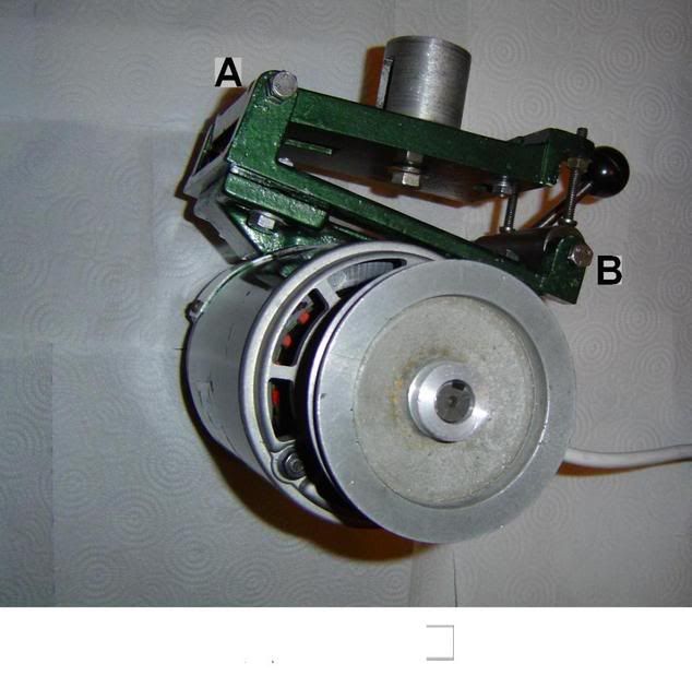
I fitted the motor to the modified cradle, and bolted the cradle to the hinged arrangement which tensions the drive belt. The big boss expands inside the cross-tube of the mill, and the lettering on this photo is explained later.
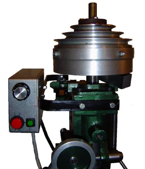
Then I fixed my electronic floggle-toggle box to the mill. The spindle head has a couple of tapped holes on the front for fixing the pulley guard. I bent up and drilled some crap DIY store 4 x 20mm flat stock so I could bolt one end to the spindle head, and the other to the flange on the other end of the Dore Westburys cross-tube. The next pic shows this, with my box of electrickery fastened to it the photo has been crudely edited to erase a confusing background, and the pulley and gearbox are chocked up to improve the view. The pulley guard is missing, but will return. I dont want an unguarded drive belt, particularly at eye level.
The motor was mounted on the Dore Westbury and the wiring temporarily hooked up for a test run. All went well at first. The combination of the 3-speed pulley drive and the variable speed motor gives a range from dead slow to whirling round far too fast for the spindle bearings.
An earlier photo is repeated here, for convenience:
The hole for the bolt through lug A on the swinging plate has a lock-nut on it below the lug, and a conical end which goes into a correspondingly shaped hole on the fixed plate with the big boss sticking out of it. Theres a similar lug and bolt below, so the fixed plate is pinched between the two bolts, which act as a hinge. The black ball-handle turns a bar which is eccentrically hinged between lug B and a similar lug below, again using cone ended bolts. The bar acts as a cam to tighten up the drive belt.
Testing came to an abrupt halt when the motor, cradle and swinging plate fell off the hinge

. Its lucky the motor wasnt running at the time, or there would have been mayhem. I thought I had located the hinge bolts properly in their holes; all seemed solid enough when given a good tug, but one of them must have missed its hole and have bitten just deep enough into the painted aluminium surface to hold temporarily.
repeated ad infinitum....
The only damage was that lug B broke off when it hit the edge of the bench on the way down. The cable to the motor acted as a safety line and stopped its headlong plunge just short of the concrete floor. Things could have been worse it might have been lug A which broke. That one takes the weight of the motor, whereas lug B isnt subject to much strain.
So, yesterday afternoons work ended with re-attaching the lug using two steel dowels and more JB Weld. Ill play safe and wait until this afternoon before disturbing it.
Andy


