Hi all,
Made a small amount of progress tonight although it doesn’t feel like I’ve done much!
When I did that test run of the flywheel on the crank in its bearings I realised there were a few minor issues.
The first one was that I hadn’t yet carried out a method of attaching the flywheel to anything!

I can’t remember why, I think I just got bored and decided to do something else! Anyway, it’s pretty essential so I decided just to use my usual method - drill an angled hole, tap and stick a bolt in it.
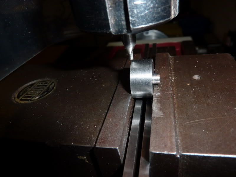
Here’s the set up on the drill (the first time I have used it during this project I think!
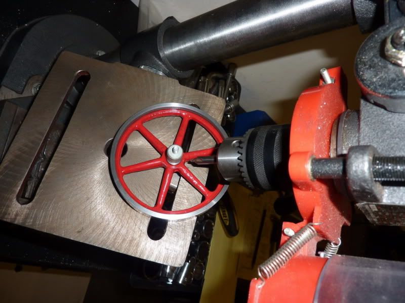
I started the taper tap off in the drill at the same setting before moving it to the vice to finish:
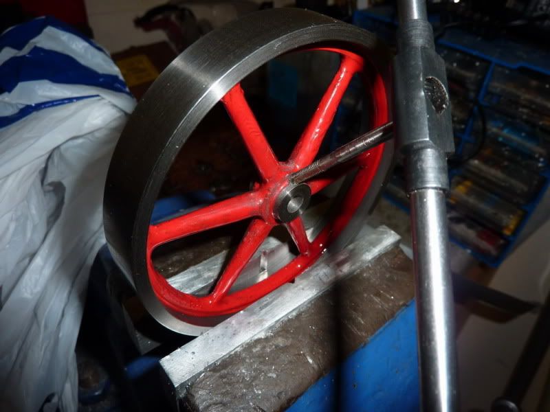
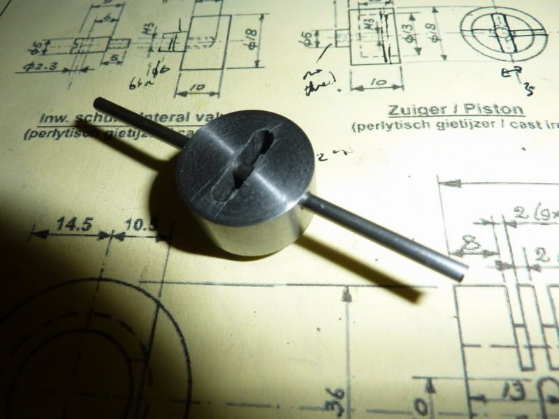
That was the flywheel done – ish! On carrying out another test run I realised something else- I the 4ba bolt to hold the flywheel on stuck out too far and fouled the bearing housing. So I just chopped it off and put a slot in it to make a grub screw.
Then there was a problem with the clearances between the bearing housings & flywheel which allowed it to move around and rub on the housing. This was because I got a bit carried away when doing the flywheel – I didn’t realise that the spokes actually have a slight curve from one side to the other, so because I was concentrating on getting the amount the boss sticks out on each side the same, the boss actually ended up narrower than the width of the flywheel!
Anyway, I decided to measure up and make some brass spacers to give necessary clearances and avoid rubbing.
I don’t have pics of the machining but I just turned some brass to a smaller OD than the boss, drilled a hole for the crankshaft and parted off. 2 x 0.5mm thick and 1 x 2.5mm thick.

That pic was straight from the lathe, surprisingly there are no burrs, which is why I picked brass. Just gave them a rub on some wet & dry after this.
I skimmed 10 thou of each side of the flywheel outer rim to avoid any rubbing with the housings. Another test build showed that when the grub screw was tightened, it made the flywheel slightly wonky –

Yes I have committed a cardinal sin! So I had to find a small piece of shim to pack under the side where the grub screw isn’t. That seems to have solved the problem. Being a cast flywheel the spokes aren’t very balanced or uniform anyway, there’s not a lot I can do about that but at least the outer runs true – ish!
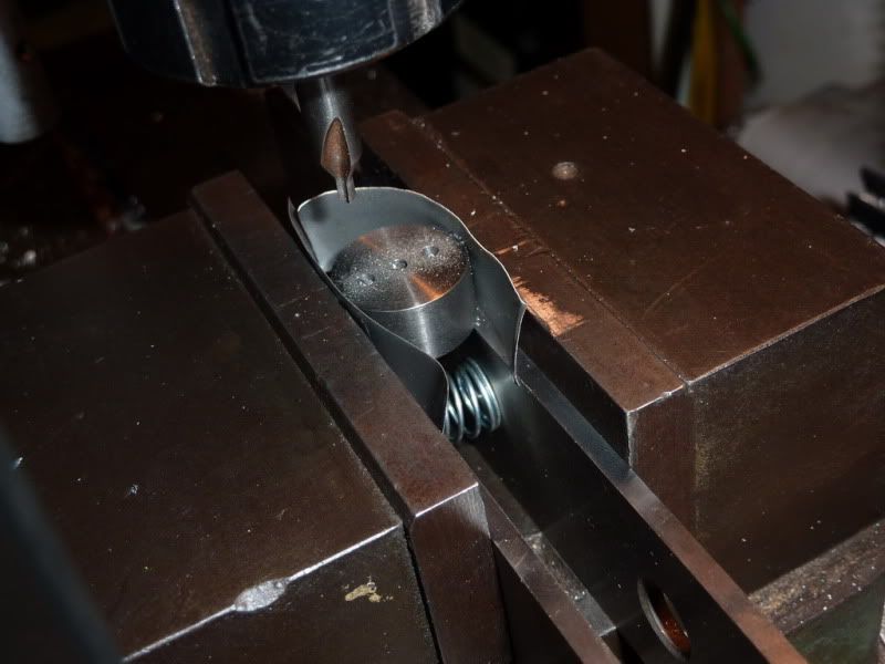
Another little niggly job that I had put off was milling the slot in the piston and drilling the hole for the gudgeon pin. So thought I might as well get that out of the way too.
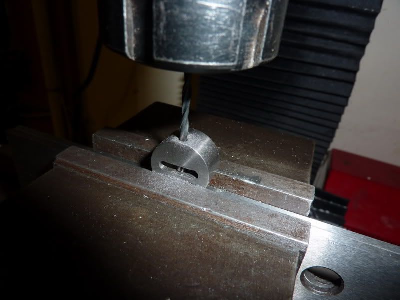
Set up in the milling vice. First I centre drilled and drilled 3 holes, 1 in centre then the 2 extremes of the slot. I should maybe have used a slightly smaller drill than the cutter but I used a slightly larger one.
Joining the holes up with the 3mm milling cutter:
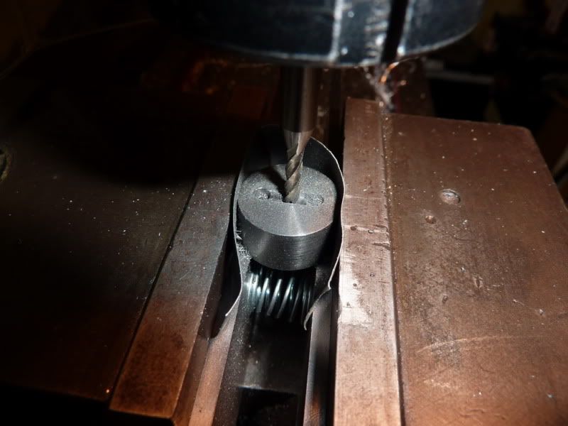
At first I started taking tiny cuts, but then thought I’d try half depth – that worked so it only took a couple of cuts. Think I could have done it full depth to be honest but I am still finding the limitations of the milling machine. I’ve given it a bit of a slagging off recently, but it actually works pretty well, it’s just not the highest quality but I guess you can’t expect that anyway. Would love a Harrison one to match the lathe!
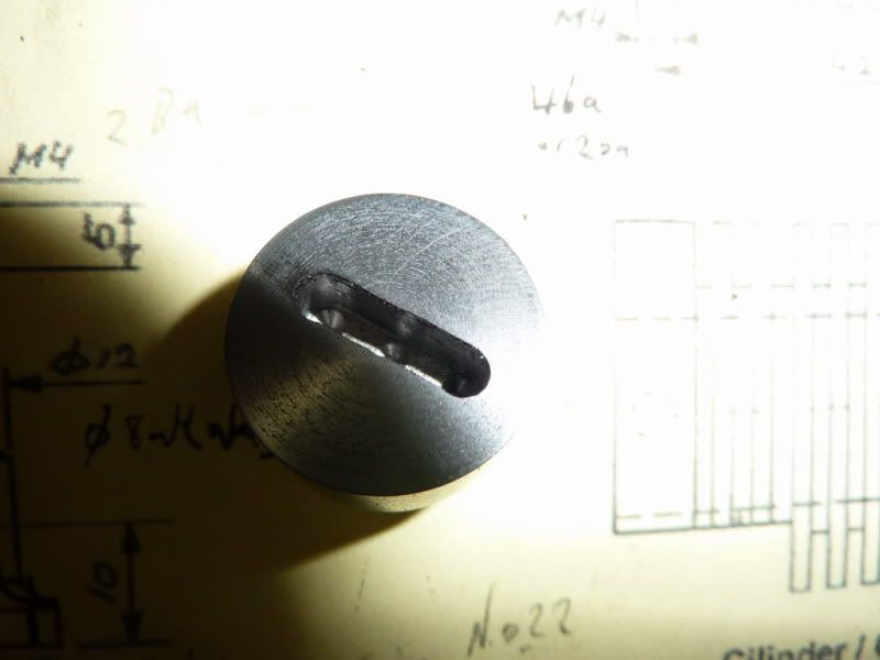
Here is a pic of the finished slot. It worked reasonably well. If I wanted a really accurate thing I would have had to use a smaller cutter then take extra cuts to come up to size. But I knew this 3mm would give a little more than 3mm, which is what I needed on this occasion. I don’t want any friction between the piston and con-rod.
Now all that was left on the piston was to drill the hole for the gudgeon pin. For this I just clamped in the mill, lining the slot up parallel to the top of the vice jaw by eye. I also just aligned the point of the centre drill to centre and edge by eye - good enough for this since there is still scope for adjustment with this engine.
Drilling the hole gently. This cast iron cuts like butter anyway though, a joy to machine.
Test fit of the gudgeon pin material. 3/32” stainless. It is a lovely free fit but no play. The steel measured 2.36mm I used a number drill that measured 2.38 on the shank.
Cut the gudgeon pin to length and faced the ends. 1mm shorter than the dia of the piston.
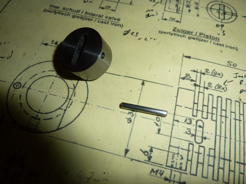
The bearing surfaces will be those in the cast iron piston, it will be a tight fit through the rod so maintaining its position in the centre of the piston.
Here’s a bit of a mock up on the aluminium that will be the base plate:
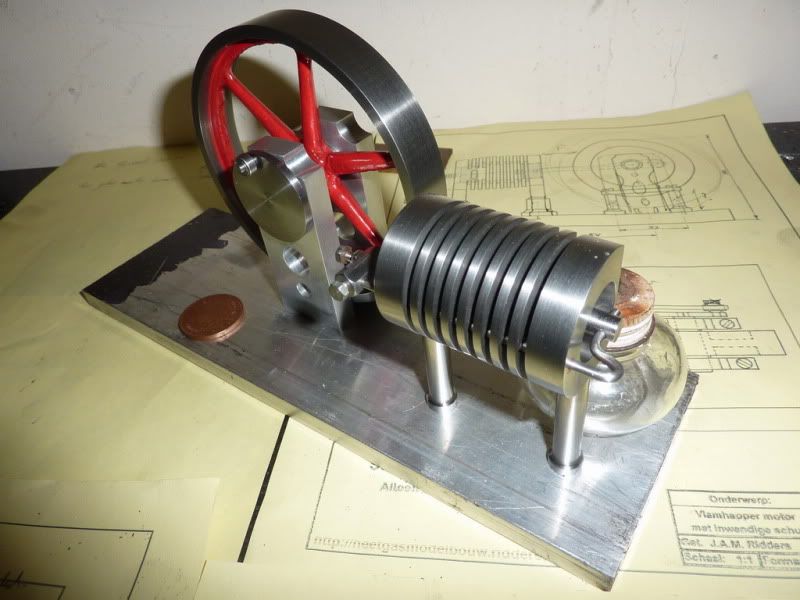
Unfortunately the glass burner I was planning on using won’t fit to give me the right flame position so I will need to make one.
I even remembered something for scale- the coin is a 2 pence piece. (Just over an inch dia)
It will certainly be the largest engine I have ever built. Can I still call it an engine if it doesn’t work?!
I’m not sure what to do with the edge of the aluminium plate. For the wooden base I will chamfer with a countersink as I liked the look of that on my rocking engine but not sure how well that will work on alloy.
Maybe I could do a stepped edge? Any ideas? Don’t think it’ll look great just square.
The finishing line is definitely in sight now I just need

to get over it!:
Con rod
Base Plate
Wooden Base
Burner
Nick


