Having read Stew's thread on a tool post spindle driven drill, I wonder whether this (very basic) item may also be of interest for dividing from the lathe headstock. Used with such a spindle drill it could prove quite a flexible and useful combination.
I needed some means of simple dividing in the lathe which would be quick and cheap to attain and not require much additional tooling/expence.
My next long term project is a large stationary engine, from a kit, which will require several dividing operations in the lathe, and my Sieg C4 is what I need to adapt for this.
There are many old ME articles around on lathe headstock dividing - using the "bull wheel" on the spindle (George Thomas/Myford attachment for one) and more recently (last year?) an article on building a simple one for the Mini Lathe in MEW.
There is no fixed "bull wheel" as such on the Sieg C4, which has turned out to be an advantage.
It seemed possible to use a few of the (supplied) change wheels for simple dividing, if a means could be found to mount them on the end of the headstock spindle.
40, 45 and 50 tooth wheels seemed to be the most useful from those supplied with the lathe.
Thanks to those articles and some new deft input from TransAtlanticDesignAssociates gave me a workable back-of-envelope design.
Here is the "kit" of bits and bobs used.

Everything has been made from (literally) scrap materials and odd off cuts - apart from the main 20mm mild steel mandrel shaft which was one of the few stock items I had on the shelf.
I started with the simple expanding mandrel to fit the 20mm headstock spindle, with a shouldered length on the outboard end of the mandrel to accommodate the internal bore of the change wheel. This is held via a nut/washer against the outboard edge of the gear wheel, the nut pulling up on the length of M8 studding holding in the tapered wedge at the other end of the tapered hollow portion of the mandrel. (Also split 4 ways down its hollowed length). The photo above should make this a bit clearer.
The shouldered portion was slotted to hold a small key to fit the chosen gear wheel.
I was fortunate to have scrounged a length of odd-leg aluminium angle bracket from a scrap bin some time ago. A length of this was hacked about a bit to fit around the pulley drive and belt on the Sieg spindle and simply mounted on a small block of steel bolted to the gearbox fire wall in the headstock (again see pics - makes it clearer).
Here is the mounting block for the bracket.
The bracket was carefully marked out for the position of the spindle and bored to a close fit.
Mounted on the block with a 40 tooth wheel on the mandrel it turned out like this.

The dividing peg and block was made from a short length of 1" sq. steel bar, drilled and reamed in part for the "fat end" - 5/16" of the peg and the tail end of the peg at the other - 5mm.
The peg was made from a short length of 5/16" silver steel, turned down at one end for the "tail".
The dividing end was carefully milled at 30 degrees in the mill, holding the peg in a simple fixture (another little parallel sided block drilled/reamed with a holding grub screw) so that both sides were the same when turned through 180 degrees in the milling vise (swivelled through 30 degrees).
In order to "double up" on dividing from the gears, I decided to make the peg to fit both in-between the gear teeth, AND sit atop each tooth - this meant very carefully slotting the end of the peg wedge end. I eventually got this using a diamond slitting wheel in my mini drill and some careful filing.
Here is the end result - a bit out of focus on macro - sorry.

The block was fitted with a pair of pins and short length of cut-off bolt (M4), using thread lock, to slide in a slot milled in the vertical face of the bracket. This allows flexibility in the positioning of the block, so as to accommodate several gears of varying diameters.
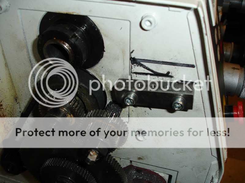
Here's a picture of the finished bracket.

I made a simple brass thumb screw from an old off-cut (hence the strange shape) and a pull-knob for the peg tail (again a bit of scrap hex).
The compression spring for the detent peg is questionable at the moment. I used what was to hand in the odds and sodds box, but must find something better. Maybe then I'll turn up a better pull-knob.
All fitted it looks like this


This is clearly looking a bit crude and certainly not blingy, but it works very well - and cost next to nothing. Time taken - a couple of days I suppose.
I don't think I have seen any thread posted on this site on simple lathe headstock dividing using a peg detent, so maybe this will give someone some ideas.
All I have done is adapt and modify previous published designs to make a cheap, simple and very flexible mechanism.
Using something like this with Stew's spindle drill, could be a very useful set up for all kinds of drilling/machining operations in the lathe , without disturbing the material held in the chuck or on the faceplate, as well as simple dividing/marking.
Peter
p.s. - I could also fit a "crank-handle" in place of the gear wheel on the end of the mandrel (having removed the block first). The mandrel can be set in the spindle a lot further out to give more clearance.
This might be useful for hand turning/slow-rev thread cutting!


