Author Topic: 1/16 scale Terramac RT7R  (Read 3439 times)

Offline ddmckee54

  • Sr. Member
  • ****
  • Posts: 373
  • Country: us
1/16 scale Terramac RT7R
« on: July 22, 2025, 08:21:42 PM »
About 3-4 months ago, my Project Muse turned into a real slave driver.  The muse decided that I wasn't busy enough, what with yard work, looking for a new daily driver to replace the one that got totaled in late April, and all the other projects the Muse already had me working on, I NEEDED another project.

I really have no one but myself to blame.  While watching the Designs In Orbit video series documenting the rebuilding of 40+ miles of the CSX railroad's track that were destroyed during the Hurricane Helene flooding, the rotating tracked dumpers were bright and shiny enough to catch the Muse's eye.  Can't really blame the Muse, they're cute little things as far as construction equipment goes.  We watched enough of the videos that we determined the rotating tracked dumpers were Terramac's RT14R. 

A 3-view was found on their website and, with a little computer tom-foolery later, I had a JPG file that I could import into Alibre and start 3D modelling the beast.  I was making pretty good progress, right up to the point where Murphy threw his monkey-wrench into the works.  You see, to save myself a lot of headaches I'd been planning on using Bruder excavator replacement tracks for the dumper.  The monkey-wrench delivery was triggered by the fact that at scale, the RT14R's tracks are over 60mm wide - the Bruder tracks are 40mm wide.  The RT14R wasn't gonna happen, this was the cause of MUCH whining and complaining from the Muse.   After about a week of the Muse's complaining, and being told that there was an RT7R on Terramac's website, AND that the Muse was positive that 7R's were also used on the jobsite...  I gave up, got the 3-views and promptly checked the track width.  Humphh... 43mm, that's close enuf for Gub-mint work.  I guess we're gonna do this thing.  In case you're wondering, this is what a Terramac RT7Rlooks like.

Like I said, cute little thing.

Design work started with the important stuff, the tracks and lower frame.  The following images show the progress of the Alibre RT7R assembly drawing as the various bits and pieces were added.


Then design work started on the dump bed.  I had noticed that I didn't have anything to keep the tracks from rubbing on the top of the track frame, so I added a guide strip.  I also added a sample track plate so I could check for future clearance issues.


The dump bed was completed , and work on the upper frame and rotating assembly was started.


The bed lift mechanism was then designed.

It took many attempts, and visiting several DIY scissor lift websites, before I had a version that could fold itself into the 21-22mm space I had available.

The working lift was then added to the 7R's assembly drawing.


By this point the back half of the model was basically done so it was time to start on the front.

TO BE CONTINUED....
Too many irons, not enough fire.

Offline vtsteam

  • Global Moderator
  • Hero Member
  • *****
  • Posts: 6819
  • Country: us
  • Republic of Vermont
Re: 1/16 scale Terramac RT7R
« Reply #1 on: July 22, 2025, 09:19:08 PM »
Interesting tailgate on that thing.

I can imagine a boulder hitting it when the dump body is halfway up. A virtue of a conventional tailgate is that it can be hinged at the top or bottom, or dropped completely. If hinged at the top and chained partially open at the bottom, a controlled dump can feed material over a longer distance as the truck moves forward. Blacktop, gravel, crushed stone. etc.
I love it when a Plan B comes together!
Steve
https://www.youtube.com/watch?v=4sDubB0-REg

Offline ddmckee54

  • Sr. Member
  • ****
  • Posts: 373
  • Country: us
Re: 1/16 scale Terramac RT7R
« Reply #2 on: July 22, 2025, 10:40:03 PM »
I started work on the engine/cab/tanks platform at the front of the machine.  This is the platform and the engine bay.


This shows the platform, the engine bay, the hydraulic oil/fuel tanks and the cab walls.


It was about this time the operator demanded that I print out his new :office chair", so he could see how well it fit his butt.

There were some complaints, the seat back needed to be tilted back, the headrest needed to be tilted forward, the top third of the headrest needed to be lopped off cause it looked STOOPID, and the joystick was located under his wrist - not in the center of his grip where it belongs.  SOOOO... the fixes were put in.

The mechanic was so pissed that he had to sit in the REJECT he said he was gonna hold his breath until he turned blue.  So far he's only managed to turn his clothes blue, but ya gotta give him an E for effort.

It was about this time that the Muse wanted to know what an opening door would look like.  I was done with the bed design so I started printing the bed parts.  This is about 9-10 hours into 14 hour print, things weren't looking good, there was a LOT of stringing.


The stringing was bad, but that wasn't the worst part.  The nominal dump bed width was 135mm, the rear section printed at 134mm, the center section printed at 139mm and the front wall printed at 136mm.  I spent 2 days trying, and failing, to correct this using the slicer's scaling.  I finally said screw the scaling, and used brute force.  I went back to the method I used to get my 1st 3D printer to actually print ROUND holes instead of ellipses.  I use the M92 command in the g-code start-up script to modify the printer's X, Y, and Z steps/mm settings.  To find out what the factory settings were, I hooked the slicer up to the printer and sent the M503 command to the printer.  That tells the printer to print the settings it has in memory back to the slicer's screen.  Next I needed a quick and easy way of calibrating a large object.  What I came up with is my calibration square, a square with 100mm outside dimensions, 2mm thick walls, and a Z height of less than 1mm.  Best of all it only takes about 2 minutes to print.  The first time I printed the square it measured about 98mm, with X being over-sized, and Y under-sized.  I made some adjustments and tried it again, this time it measured in at about 99.5mm.  One final tweak and it measured 100.1mm, +/-0.05mm in both X and Y.  Close enuf for Gub-mint work.  Once I finally gave up on the slicer's scaling, it took less than 2 hours to do what I failed to do in 2 days using the slicer's scaling.  This is the completed dump bed parts.


It was about this time that the Muse decided I needed a "side project", a working hidden hinge for the engine bay door.  After about 3 days and many failed attempts, I finally had a design that worked.


So I printed out the last of the yellow parts.  Here's a family photo.


The operator was so excited he decided to jump in and take his new ride for a spin.  When it wouldn't start he called the mechanic over to check out the problem.  When the mechanic popped open the engine bay door he started yelling, "We've been robbed, we've been robbed!  They took everything." 

I'd have liked to get a little more of an opening, but there's only so much that you can get folded into a 10mm thickness.

That's it for the yellow parts, on to the grey.

TO BE CONTINUED....
Too many irons, not enough fire.

Offline ddmckee54

  • Sr. Member
  • ****
  • Posts: 373
  • Country: us
Re: 1/16 scale Terramac RT7R
« Reply #3 on: July 22, 2025, 10:44:09 PM »
vtsteam:

The tailgate is optional, I decided to delete that option on mine.  They don't usually put them on the "rock: beds.

Don
Too many irons, not enough fire.

Offline ddmckee54

  • Sr. Member
  • ****
  • Posts: 373
  • Country: us
Re: 1/16 scale Terramac RT7R
« Reply #4 on: July 23, 2025, 12:30:14 AM »
The grey parts, there's so many of them, where to start... the cab, THE CAB.  The  operator has been complaining about the cheap-skate boss who won't even put a roof over his head.  That'll put him in his place - literally.  I ran the calibration square using the grey filament and made the required changes.

Now, not only has he got a roof over his head, he's got 4 walls, a floor and a control panel - with buttons and knobs to play with.  Unlike Les Nessman's office, the walls do not involve masking tape on the floor.  I guess that masking tape is sort of involved, since that's what's keeping the floor from dropping out from under his feet.

Onto the BIG grey pieces.

What we have here are the major parts of the lower rotating assembly.  Clockwise from the right they are: the main frame, the slew gear - with the slew bearing installed, the slew gear spacer. and the upper slew bearing clamp.  The upper slew bearing clamp, slew gear, and slew gear spacer will get bolted to the main frame, the pockets for the M3 heat set inserts are visible in the main frame.  The big hole in the main frame is where the slip-ring that feeds the track drive gearmotors will live.  The upper slew bearing clamp keeps the slew bearing from pulling out of the slew gear and firmly attached to the main frame.  A lower slew bearing clamp will live in the large hole in the slew gear spacer.  That clamp will keep the upper half of the rotating assembly firmly attached to the slew bearing, and all will remain right with the world.  The key-hole shaped notch in the slip-ring hole gives me access to install the M3 screws that will bolt the lower slew bearing clamp to the upper center frame.  Since that picture was taken another couple of piles of grey parts have been added, 17 bogie side plates, and 10 bogie wheels.  I meant to print 2 extras of each, but I only printed 1 extra side plate.  The printer is currently 6 hours into an 8 hour print on the engine bay base and the tanks bay base. 

This will give you some idea of what's under the hood in the engine bay and tank areas.


Side project #(??? - I don't know, I lost count.)

This was a test to see if you can easily replicate an open grid using an FDM printer, and yes Virginia, you can.  This would normally be a solid object 2mm thick with a grid infill pattern.  However, when you tell the slicer to use 0 bottom layers and 0 top layers, you get the above.  Then I got to wondering if I could use a variation on that to print something like this.


Turns out yes you can.

These two used almost the same STL file as the 1st experiment, only the thickness was reduced from 2mm to 0.6mm.  They were both printed with 0.2mm layers, 2 bottom layers, and 0 top layers - which left 1 infill layer.  The guy on the left was printed at 30% infill while the guy on the right was printed at 75% infill.  With my 0.4mm nozzle that's way too small, 60% might be about as small as I'd go.

I've still got a lot of grey parts to print, the idler assemblies with the track tensioners included, the bed lift assembly, plus God only knows what else.  Then there's the black doo-dads to print, the fuel fill cap, the hydraulic tank vent, the exhaust stack, the front guard rail, the headlight covers, the work platforms...

But that is the current state of affairs with this project.

Don
Too many irons, not enough fire.

Offline vtsteam

  • Global Moderator
  • Hero Member
  • *****
  • Posts: 6819
  • Country: us
  • Republic of Vermont
Re: 1/16 scale Terramac RT7R
« Reply #5 on: July 23, 2025, 09:38:07 AM »
That's very impressive work, to say the least!!  :clap:  :bow:  :beer:

I love it when a Plan B comes together!
Steve
https://www.youtube.com/watch?v=4sDubB0-REg

Offline vtsteam

  • Global Moderator
  • Hero Member
  • *****
  • Posts: 6819
  • Country: us
  • Republic of Vermont
Re: 1/16 scale Terramac RT7R
« Reply #6 on: July 23, 2025, 09:40:59 AM »


I like the fact that you added a backhoe to the engine bay in black. Must make the vehicle very versatile!
I love it when a Plan B comes together!
Steve
https://www.youtube.com/watch?v=4sDubB0-REg

Offline ddmckee54

  • Sr. Member
  • ****
  • Posts: 373
  • Country: us
Re: 1/16 scale Terramac RT7R
« Reply #7 on: July 23, 2025, 12:08:53 PM »
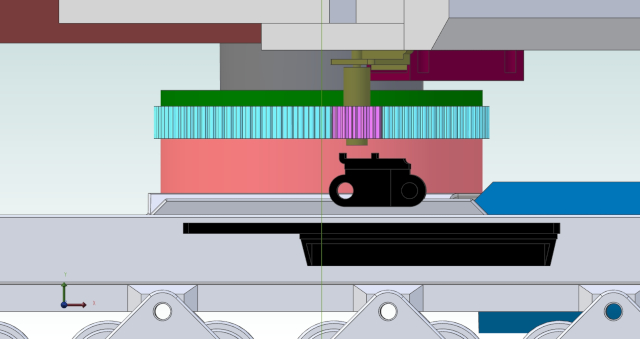
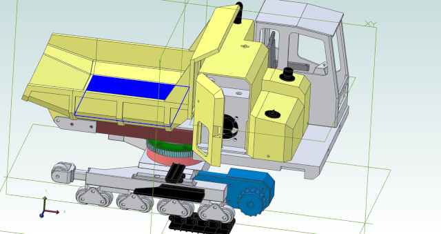
I probably should have explained what the objects in the cross section view through the engine bay and tank areas, actually were.


If you haven't already figured it out, the yellow object in the background is the bottom of the dump bed.  The green object in front of it is the bed lift mechanism.  The cyan colored object is the 10 channel receiver, I'll only be using 7 channels though.  The red objects, below and to the right of the receiver, are a pair of 6V, 2400mAH, NiMH battery packs that will be wired in parallel.  (Should give me plenty of run time.) 

The black object in the engine bay, below and to the left of the receiver, is the cooling fan.  It will suck air through the hole in the engine bay door.  The cooling air will be directed, by various bulkheads and baffles, first over the track drive ESC's, then over the ESC's for the bed lift motor and the slew motor, then over the batteries, before exiting through openings in the cab side of the engine bay.  The track drive ESC's aren't visible in this picture, but they will live on the left side of the grey baffle in the tanks.  That baffle is visible over the upper edge of the cross section in front.  The other ESC's are BARELY visible, they are the orange bits that are just peaking over the cross section edge on the right side of the tank baffle.

That takes care of the upper part of the rotating assembly, now we'll drop down to the lower part.  The dark blue object is the LH track drive gearmotor.  The grey object in front of the gearmotor is the LH track frame assembly.  The four bogie assemblies are below the frame, and the track tensioner/idler roller is on the far left,  The bogie rollers and the idler roller will a run on a pair of 5mm ID x 9mm OD ball-bearings.  The black objects below the bogies are a section of the track plates, so I could verify clearances.  The purple object on top of the track frame is the guide strip that keeps the track from rubbing on the frame.  The black bit on top of that is a track plate, this allowed me to check clearances between the upper rotating assembly and the lower rotating assembly.  I've got about 2mm of clearance now but if I need more, I'll print a new slew gear spacer that's a couple mm thicker - Eazee-Peazee.

I thought that I had a better, more recent cross section view that ACTUALLY shows what's under the hood, but apparently I didn't save that image. If you want to see it, I can upload that newer view along with the cross section that shows what's buried inside the actual rotating assembly.

Don
Too many irons, not enough fire.

Offline ddmckee54

  • Sr. Member
  • ****
  • Posts: 373
  • Country: us
Re: 1/16 scale Terramac RT7R
« Reply #8 on: July 24, 2025, 11:16:44 PM »
OK, OK... so I made a door for the cab. I told the Muse I wasn't going to make a WORKING door, and I DIDN'T. Instead I made a door skin, and some fake hinges that got glued on to the side of the cab.

It looks better in real life. The flash washes out all the shadow lines, but it does let you see the operator much better. I may still take my plastic scriber and scribe around the door, now that I've got a good solid edge to guide the scriber. Or I may not, depends on how ambitious/lazy I feel.
Too many irons, not enough fire.

Offline John Rudd

  • Hero Member
  • *****
  • Posts: 2539
  • Country: gb
Re: 1/16 scale Terramac RT7R
« Reply #9 on: July 25, 2025, 07:24:02 AM »
Looking good... :clap: :thumbup:
eccentric millionaire financed by 'er indoors
Location:  Backworth Newcastle

Skype: chippiejnr

Offline ddmckee54

  • Sr. Member
  • ****
  • Posts: 373
  • Country: us
Re: 1/16 scale Terramac RT7R
« Reply #10 on: July 28, 2025, 03:50:51 AM »
In the last couple of days I've been busy figuring out how I could modify a 13 rpm 3D pen's extruder drive, with a worm gear output for the final drive, into my slew motor.  Also figuring out just how much other stuff I'd need to modify, because SOMEBODY didn't bother to figure this out BEFORE he slapped everything together in the assembly drawings.

Fortunately, none of the modifications were extensive.  The 3D pen extruder has a worm output gear, and a straight cut gear, both are pressed onto what looks to be about a 1.5mm shaft.  What I am starting with looks very similar to this.

I had to order a small gear puller set that will allow me to pull the gears off the shaft, and press everything back together when I'd done with the modifications.  I'll need to make a new output shaft, one that's nearly 20mm longer than the existing shaft.  I've no doubt that I'll need to order some stock to make that shaft.  I also need to go from the 1.5mm shaft to a 4mm shaft, for the 14T GT2 pulley that I'm using for my slew gear pinion gear.  I've got some 5mm stock I'll use for that.

I discovered that some how, somewhere along the line I had changed my mind about exactly where I was going to put the slew motor.  I started out with the planned location being on top of the platform.  I think it probably changed about the time I decided to put a seat, and an operator, and a control panel in the cab.  Because some Doofus didn't 3D model this change at that time, when I got around to it - I was in trouble.  By that time I had received the 14T pulley, which was also about 12mm longer than I was expecting - I can only get rid of about 4mm of that 12.

BUT... I've still got to bury the slew motor gear box, which is 10mm thick, into the upper frame - which is 12.7mm thick.  AND, has 5mm deep wiring tunnels dug right where the slew motor needs to go.  I can sink it about 5mm into the upper frame. but I need to gain at least another 5mm somewhere - maybe more.  I added another 5mm to the height of the spacer ring that positions the slew bearing, modeled the 14T pulley as short as I could get it, and checked the 3D model for interference.  I still had interference between the tracks and the bottom of the slew pinion - so I added another 2mm to the spacer ring.  I now have 1.7mm clearance between the tracks and the slew pinion as the pinion rotates over the tracks.  (That's good enuf for Gub-mint work!)

Between the slew motor debacle, and the GT2 pulley being 12mm longer than expected, I had to add over 9mm to the space between the upper and lower frames.  It's starting to look a little ODD.  I think I can lose some of that extra height by eliminating the upper and lower slew bearing clamp rings, which are both 3-4mm thick.  The upper clamp ring holds the inner race of the slew bearing to the upper frame, while the lower ring holds the outer race to the lower frame.  The rings are each held on by six M3 button head screws.  If I eliminate the rings, and use the just button head screws - and flat washers - to hold the races in place, I can probably lose about 6-7mm of the extra 9 that I added.  Which should help to eliminate the too tall look.  But doing that means I need to change the positions of the pockets for the heat set inserts in the lower frame - which is already printed.  (Nope not changing that one, maybe just the upper clamp ring?  We'll see.)

Don
« Last Edit: July 28, 2025, 04:57:43 AM by ddmckee54 »
Too many irons, not enough fire.

Offline jiihoo

  • Jr. Member
  • **
  • Posts: 71
  • Country: fi
  • Finland - Northern Europe
Re: 1/16 scale Terramac RT7R
« Reply #11 on: Today at 05:40:56 AM »
You do fine modeling work. Enjoying following this!