Just a concept so far:
Although Paint has to be among the best programs ever offered by Microsoft (it just does what it is supposed to do and does not try to take over your life) it does have some deficiences when used as a CAD program!

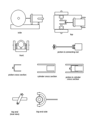
The engine, it is a single acting steam or air engine with piston valving, it is not reversable but it should have good efficiency and be able to make good use of expansion of the steam or compressed air, I doubt it would run well on low pressure air but it should be economical on the use of steam or air. In elecrical terms it would be a high impedance engine!
The piston is a hollow cylinder closed at the rear/bottom and moves inside a cylinder which incorporates a fixed displacer so that when the piston is TDC the internal volume is a low as possible. The piston has clearance around the displacer, this clearance is a trade off between minimum TDC volume and friction of internal air/steam flow. The effective diameter of the piston is the full diameter.
The engine has an air/steam input port on one side and exhaust port on the other. The location of the ports coincides with the inner limit of the displacer.
Holes in the sleeve part of the piston pass by the ports and so provide the valving action.
The big end bearing is mounted at an angle to the crank pin and is connected to the connecting rod via a pivot, the connecting rod is connected to the piston by a universal joint.
As the crank rotates the angled big end bearing acts as a swash plate and causes the connecting rod and hence the piston to partially rotate. This rotation, which reverses each half crank revolution, means the path followed by the piston ports is different on the up and down strokes and gives scope for setting the port timing for desired operating characteristics.
In this engine, being single acting I have designed the port openings to be inlet open from TDC till some yet-undetermined angle and for exhaust to be open for most of the up stroke. I dont believe such asymetric valve timing can be achieved in other simple designs such as the oscillator engines.
To actually fix the position of the piston ports I intend assembling the engine including the ports in the cylinder then marking with a felt pen or something through the cylinder ports as the crank is rotated, I will then take the piston out and drill the piston ports. The exhaust port will be a series of holes or a slot (depending on how clever I feel on that day) while the inlet port will likely be just a single hole. If I find the minimum air pressure to run is too high I will elongate the inlet port in the piston somewhat to get a longer input opening duration.
There is another engine design on-line with a semi-rotating piston but I am unsure if it has symetrical valve timing and uses a different method to control piston movement.
I have started to make the cylinder and to gather the bits, it will not be a tiny model as there is a limit as to how small I can make the big end bearing and besides I dont intend making it too hard as a first project by trying to work in tiny size.
Ah yes, nearly forgot, 'nutation' is the motion a coin takes when spun on the table and also the motion of a planet which wobbles on its axis (which the Earth does due to tidal effects). This engine has a nutating big end!


