Author Topic: Bog's Paddleduck Engine  (Read 98861 times)

Offline kvom

  • Hero Member
  • *****
  • Posts: 520
Bog's Paddleduck Engine
« on: April 28, 2009, 08:10:32 PM »
I have abandoned the CO2 engine, as I have come to believe that the laws of physics will prevent me from getting it running.  Some things don't scale up well.   :scratch:

I think I will have a go at the Paddleduck plan Bogs posted on HMEM.  I'l let this thread be a placeholder until I actually make some parts.

My current idea is to scale it up by 1.5 times and use Imperial threads and fasteners (I have a lot of 5-40 and 6-32 screws and nuts).  I will also use non-metric drill rod in places where that's called for.  Otherwise I will just multiply the dimensions by 1.5 and convert to inches.  I have a DRO on both the mill and the lathe, so odd numbered lengths shouldn't be a problem.

I will also go somewhat for the "bling" look.  I probably won't try the separated cylinders as I don't yet have a good rotary table, and as I will be running it on air and not steam I think I can skip the displacement oiler.  I'm pretty sure I have enough scraps lying around for most of the pieces (I plan to do the block in steel rather than cast).

I've skimmed through the "book" once, but now I'm going to read it more carefully before starting out.  The printer is going as I type.

Offline websterz

  • Sr. Member
  • ****
  • Posts: 415
Re: Bog's Paddleduck Engine
« Reply #1 on: April 28, 2009, 08:12:51 PM »
Why go up? Scale it down 1:3...that'll be fun! :thumbup:
"In the 60's, people took acid to make the world weird.  Now the world is weird and people take Prozac to make it normal."
 :med:

bogstandard

  • Guest
Re: Bog's Paddleduck Engine
« Reply #2 on: April 28, 2009, 09:43:38 PM »
K,

John S did a double sized V twin, the same as yours. He had a little trouble getting it to run. A change to running on high pressure actually got it turning over OK. The lift pin lengths are super critical.

Shred over on HMEM is building one of my engines at this moment, and he is doing the Imperial conversion as well, but he isn't finding it too difficult, except metric has a better range in the smaller sizes of screws, so he is basically sticking to two Imperial ones.

Darren on here is getting along fine as well, but he is doing the metric version using purely marking out and manual handle settings on the machines. So you having DRO's is a distinct advantage.

If you are enlarging it, you should find no problems, as the engine has lots of adjustments in critical areas, and on the valve gear itself, you make the spools to the correct spacings by measuring between your drilled holes.

Good luck with your project, and if you have any troubles, you have the correct person reading your postings about it, and will help if it is needed.

Because you are running on air, you can make it out of almost anything you have in your scrap box. As long as it will take the pressures involved, use it.


Bogstandard

Offline kvom

  • Hero Member
  • *****
  • Posts: 520
Re: Bog's Paddleduck Engine
« Reply #3 on: April 28, 2009, 10:08:42 PM »
Quote
John S did a double sized V twin, the same as yours.

Unfortunately mine is 3x, as I was seduced by a cube of aluminum that was "just the right size" for the crankcase.   :bang:

My other build was Elmer's bream engine in double size, with the plans that Brian Rupinow provided.  I followed his dimensions but varied the style quite a bit.  It ran fairly quickly after I finished the assembly.  Your engine has more parts, but I don't see any that are significantly more complex.  I'm used to making the harder ones over and over anyway.   ::) 

bogstandard

  • Guest
Re: Bog's Paddleduck Engine
« Reply #4 on: April 28, 2009, 11:29:31 PM »
Kvom,

There is only really one difficult part to make, and that is the crosshead, but if time is taken to think about it as it is being made, even that becomes a simple job. The normally difficult bits, like the crankshaft, uses the method of, a few simple things, that when brought together, make one complicated part.

With your experience, I don't see you having any problems at all.

When finished, it is a lovely runner, even more so if it was to be made larger.


Bogs

Offline sbwhart

  • Global Moderator
  • Hero Member
  • *****
  • Posts: 3530
  • Country: gb
  • Smile, Be Happy, Have Fun and Rock Until you Drop
Re: Bog's Paddleduck Engine
« Reply #5 on: April 29, 2009, 01:22:25 AM »
Hi Kvom

Look forward to seeing your build, I'm planning on building one of those engines later in the year as a break for my loco build, (when I start on it again)

Have fun

Stew
A little bit of clearance never got in the road
 :wave:

Location:- Crewe Cheshire

Offline kvom

  • Hero Member
  • *****
  • Posts: 520
Re: Bog's Paddleduck Engine
« Reply #6 on: April 29, 2009, 08:10:26 AM »
I might try to make the crossheads first to get the harder parts done first.   The other parts that are new to me are the eccentrics and silver soldering.  I made the eccentric on the beam engine in two pieces, but I should bite the bullet and get the 4-jaw chuck on the lathe.  Not rocket science, but tedious to adjust.

A question to make sure I understand the workings:

The writeup on the crank webs states that the dimensions are critical.  I believe that this is because the distance between the two holes determines the total displacement of the piston in the block and hence must match the location of the steam inlet/outlet holes.  Is this correct?  Assuming this, are the diameters of the two rods that comprise the crankshaft also critical?  Or in other words, can the shaft and the journals use the same diameter rod?

Offline Darren

  • Madmodder Committee
  • Hero Member
  • *****
  • Posts: 3795
  • N/Wales
Re: Bog's Paddleduck Engine
« Reply #7 on: April 29, 2009, 08:21:35 AM »
The diameters should make no difference to the throw as this is measured center to center of the rods.....within reason you should be able to make them whatever you like.

Just bear in mind, bigger dia, bigger surface area, friction/load bearing surface area the two main criteria to be concerned with here.
You will find it a distinct help… if you know and look as if you know what you are doing. (IRS training manual)

Offline kvom

  • Hero Member
  • *****
  • Posts: 520
Re: Bog's Paddleduck Engine
« Reply #8 on: April 29, 2009, 08:30:53 AM »
Thanks for the quick reply Darren.  I was just reading through your thread, and hadn't realized you were now building to John's plans as well.  Looking good!

I now realize I will need a slitting saw and arbor for the mill to make the crank webs.  Luckily Enco has a free shipping deal going on.

Offline Darren

  • Madmodder Committee
  • Hero Member
  • *****
  • Posts: 3795
  • N/Wales
Re: Bog's Paddleduck Engine
« Reply #9 on: April 29, 2009, 08:47:47 AM »
In that case this may be of interest  :thumbup:

http://madmodder.net/index.php?topic=646.0
You will find it a distinct help… if you know and look as if you know what you are doing. (IRS training manual)

bogstandard

  • Guest
Re: Bog's Paddleduck Engine
« Reply #10 on: April 29, 2009, 09:28:47 AM »
Kvom,

If you read the writeup on making the eccentrics, you don't need to use the four jaw, but your mill.

With regards to being critical with the dimensions on the crankwebs. That is because if you don't get the hole centres the same as each other, either the crank won't turn or will wobble all over the place.

If you follow the writeups in the book, it shows exactly how to obtain the correct results, no guessing, no magical solutions, just the correct way to get what is required. Plus with you having DRO's, you should be able to do it with your eyes closed.


Bogs

Offline kvom

  • Hero Member
  • *****
  • Posts: 520
Re: Bog's Paddleduck Engine
« Reply #11 on: April 29, 2009, 11:05:32 AM »
My question was  the "engineering" that went into the design.  Since you made the block first, did the dimensions for the webs come from the inlet/outlet spacing?  My assumption is that the offset of the eccentric is likewise tied to hole spacing in the  steam chest.  The entire subject of valving in steam/air engines is fascinating.  When building the Elmer engine, I just went along blindly following the plans, drilling holes wherever indicated, happy as a clam.  It wasn't until I actually looked at the cross-section of the valve and cylinder bore in Elmer's original plan that I had any inkling how it was supposed to work.

Offline Darren

  • Madmodder Committee
  • Hero Member
  • *****
  • Posts: 3795
  • N/Wales
Re: Bog's Paddleduck Engine
« Reply #12 on: April 29, 2009, 11:19:33 AM »
I don't have an inkling how this all works either, I'm hoping my build will show me the way it all fits  :ddb:
You will find it a distinct help… if you know and look as if you know what you are doing. (IRS training manual)

bogstandard

  • Guest
Re: Bog's Paddleduck Engine
« Reply #13 on: April 29, 2009, 01:44:06 PM »
Now I understand where you are coming from Kvom.

In fact, when I designed this engine, I had never worked on a piston valve one before, and I asked around for any formulae, and Sandy (in the book) made some suggestions about timing and porting. From that information I worked everything out myself.

The relationship is the total eccentric lift (6mm), the spool lengths (3mm) (the length of the thick bits on the spindle that goes up and down in the valve block) and the diameter of the holes (3mm) that the thick bits open and close.

When I get a bit more time in the next couple of days, I will knock up a sketch how it all works in unison.


Bogs

Offline kvom

  • Hero Member
  • *****
  • Posts: 520
Re: Bog's Paddleduck Engine
« Reply #14 on: April 29, 2009, 08:11:48 PM »
OK, I have one part made to justify this thread.  I decided to tackle the eccentrics, as the technique in the book is interesting.  I also had some suitable sized steel cutoffs.

In interpreting the plans I calculated that 1.5mm = .059", so any dimension needed is quickly calculated needing to remember only one number.  So the diameter of the eccentric is 18mm -> 1.06".

The initial turning to length and cutting the end flange and groove were not too difficult.  I recently acquired a very veteran B&S height gauge and a cheap ENCO granite surface plate, so that I was able to measure the lengths and face to the desired dimension fairly easily, if slowly.

I don't have a rotary table, but I used the following setup clamp the disc in the mill vise and to find the center quite rapidly:


The indicated 5mm hole defines the diameter of the crankshaft, and so would fall between 1/4 and 5/16 inches.  I happened to have some 1/4" drill rod, so that's the size it will be.  That said, I can always enlarge the hole should a thicker crankshaft be needed.

Then my trouble of the day started, as my run-of-the-mill automotive class die was incapable of cutting a 1/4-20 thread in the end of the hardened rod.  So I had to resort to trying to thread the rod using the lathe.  Once the threading tool cuts through the hard layer the interior of the rod is a rather gummy steel that resists cutting cleanly.  So after any number of tries I finally got some partial threads cut and was able to finish them with the die.   Then it was a matter of bolting the eccentric piece against the face of the 5C collet/block as shown here:


The reason for this setup is that the 6-jaw vise won't tighten on a 1/4" rod, so this is my "collet chuck" setup for small rods.  The chuck is very accurate, so that the runout with this setup is quite low.  It's necessary to really tighten the collet when taking the interrupted cut or else the rod will just turn in the collet jaw.  My turning technique was to touch the lathe tool to the innermost point of the boss and set the DRO y-axis to zero.  Then when turning I could watch the DRO count down and would know when to stop the cross feed, which was running at the lathe's slowest speed of .0006/revolution.

So after 4 hours work I have 1 part to show:


I used a lock washer under the bolt, which scratched the surface a bit.  For the next one a flat washer might be better.

And of course as soon as I was finished I remembered that I had a piece of 1/4-20 threaded rod that I could have used instead of threading the drill rod.

At least I'm "underwauy"  :proj:

bogstandard

  • Guest
Re: Bog's Paddleduck Engine
« Reply #15 on: April 29, 2009, 10:42:24 PM »
Very nicely done Kvom, I had forgotten I had used the RT, but you soon cured it by finding the centre in the vice.
Doing it this way saves all the hassle of setting up in the 4 jaw.


Bogs

Offline sbwhart

  • Global Moderator
  • Hero Member
  • *****
  • Posts: 3530
  • Country: gb
  • Smile, Be Happy, Have Fun and Rock Until you Drop
Re: Bog's Paddleduck Engine
« Reply #16 on: April 30, 2009, 01:10:56 AM »
Well done that Man  :clap: :clap:

That six jaw chuck looks an andy beast  :thumbup:

Stew
A little bit of clearance never got in the road
 :wave:

Location:- Crewe Cheshire

Offline kvom

  • Hero Member
  • *****
  • Posts: 520
Re: Bog's Paddleduck Engine
« Reply #17 on: April 30, 2009, 05:44:51 PM »
Today I fabricated the other eccentric using the threaded rod.  It went much faster, about an hour start to finish.

I then went through the book noting the dimensions, calculating the 1.5x dimensions and writing them on the pages, and comparing these to the brass material I have on hand.  It seems I either have pieces that are too small, much too big, or else I need to make a part to fit another part that gets made first.

However I do have a number of pieces of 1/4" thick brass sheet that was originally 3" wide.  Since I now had the eccentrics made it seemed logical to make the straps next.  I found two pieces that were reasonably close to the top and bottom sections, squared the sides on the mill, measured each with the height gauge to calculate how much needed to be milled off, and then milled both to the calculated size.

The only point of interest to a reader might be this "technique" for clamping a part in the mill that is thinner than your parallels:


These hardened precise cylinders are also useful in ensuring proper clamping when the surface against the moveable jaw is not flat.

Once both pieces were sized and precisely squared, I drilled the holes for the screws.  I am using 6-32 screws.  Once the top piece was drilled and tapped, and the mounting surfaces deburred, I screwed the two tightly together and camped in the vise in order to bore the hole. 

The diameter of the groove in the eccentrics is ~.830, so I wasn't going to be able to find a "lucky fit" drill bit as Bogs did.  So after edge finding to locate the center of the bore, I center drilled and drilled through with the 1/2" drill bit.  Then I remembered that I have a .75" end mill, and used this to enlarge the hole further.  Then I had to resort to the boring head to reach the final dimension.  I recently acquired a set of bore gauges, and these were immensely useful in measuring the bore with the piece still in the vise.  I used Bogs' tolerance of .05mm, which is ~.002.

Next I used a 1/2" endmill to reduce the thickness of the strap (still screwed together) to fit the width of the groove in the eccentric, taking equal amounts on both sides.  This also cleaned up the surface on the sides.

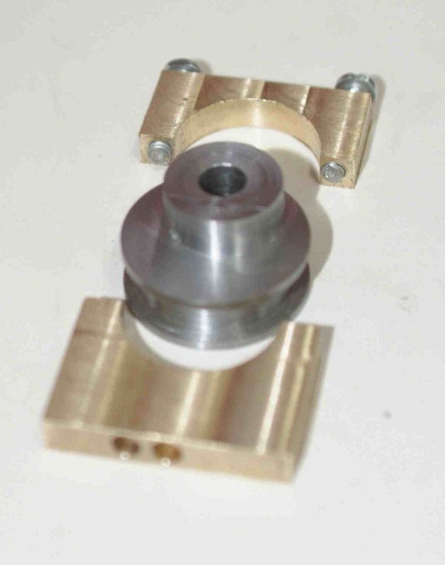
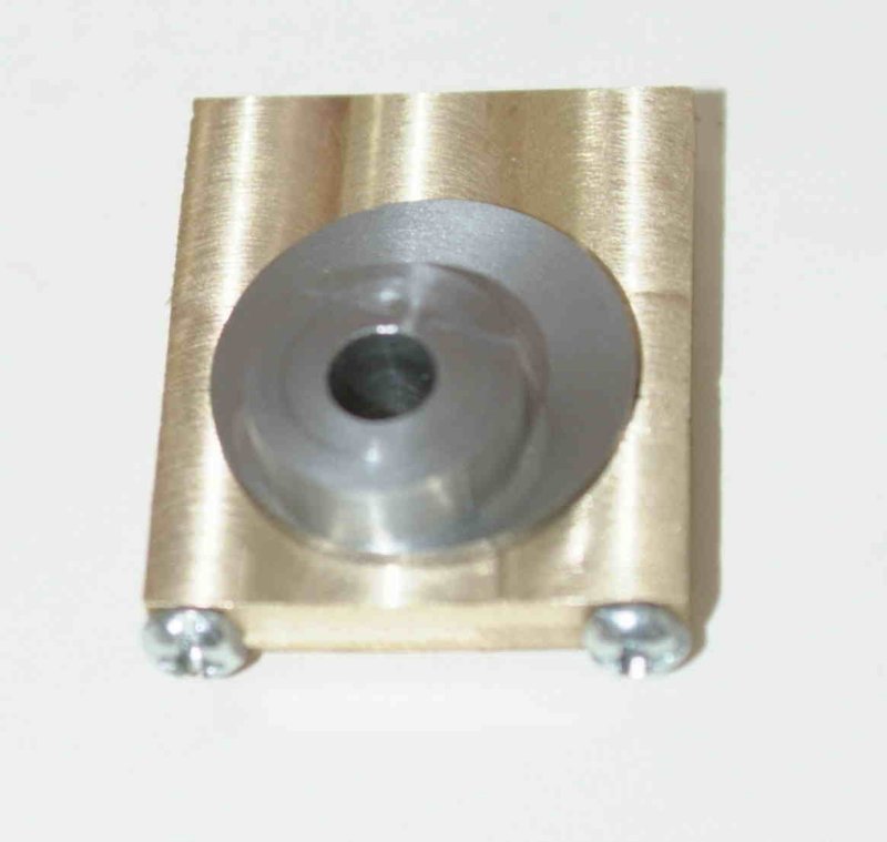
When assembled onto the eccentric it turned, albeit stiffly.  Some lapping and run-in should take care of the fit (I hope).

Then I reclamped the top portion in the vise to drill the holes for the coupling.  It seems that 3/16" rod would be a bit too big, so I drilled it 5/32.  Then drilling the oil hole completed the day's shop activity.  Here's the result of about 5 hour's work:


Offline Brass_Machine

  • Administrator
  • Hero Member
  • *****
  • Posts: 5504
  • Country: us
Re: Bog's Paddleduck Engine
« Reply #18 on: April 30, 2009, 08:24:16 PM »
On your way sir!

I want to do this one... hell, my list keeps getting longer and longer!

Eric
Science is fun.

We're all mad here. I'm mad. You're mad.

Offline kvom

  • Hero Member
  • *****
  • Posts: 520
Re: Bog's Paddleduck Engine
« Reply #19 on: April 30, 2009, 10:14:21 PM »
I went through the book and made a list of all the parts, compiling them into a spreadsheet.  Here's the results.  Useful as a checklist:


   Parts List for Bogstandard Paddleduck Engine   

Part   Qty   Dimensions   "Page #"

"Main Block"   1   54x32x18   3
Top Cap   2   18x2.5+   11
Packing Gland   2   18x8   11
Packing Gland Adjusting screw   2   8x8   11
Piston   2   10x5   12
Crosshead   2   27x22x16   12
Piston Rod   2   3x10   12
Top Plate   1   64x50   16
Crosshead Guide Bars   2   4x39   18
Bearing Block   4   20x15x10   19
Baseplate   1   110x50   22
Crankwebs   4   28x5   24
Flywheel   1   32x10   24
Eccentric   2   18x10   30
Support Columns   4   6x10.5   32
Support Pin (if needed)   6   4x12   32
Connecting Rod   2   35x6.5x6.5   32
Steam Chest   2   40x18x16   35
Steam Chest Blanking Plate   2   32x18x2   42
Spool Valve   2   6x45   48
Eccentric Strap Bottom   2   21x10   53
Eccentric Strap Top   2   21x15   53
Eccentric Coupling Block   2   10x6x4   53
Eccentric Coupling Fork   2   6x4x4   53
Piston Valve Packing Gland   2   12x9   55
Piston Valve Screw   2   8x8   55
Steam Flange   4   12x6   57
Steam Flange Base   4   12x4   58
Steam Control Block   1   25x25x10   65
Steam Control Spool   1   10x23   70
Steam Control Bottom Plate   1   22x7   70
Steam Control Top Plate   1   22x10   70
Steam Control Arm   1   26x7x5   70
Lubricator Body   1   15x30   73
Lubricator Top   1   15x14   73
Lubricator Screw Cap   1   8x8+   73

74 parts in all.  I didn't include rods, tubing, or fasteners that don't require fabrication other than cutting to length.

Offline Darren

  • Madmodder Committee
  • Hero Member
  • *****
  • Posts: 3795
  • N/Wales
Re: Bog's Paddleduck Engine
« Reply #20 on: May 01, 2009, 04:26:22 AM »
I've done 11 of them  :)

Only 63 to go, see nearly finished  :lol: :lol: :lol:
You will find it a distinct help… if you know and look as if you know what you are doing. (IRS training manual)

bogstandard

  • Guest
Re: Bog's Paddleduck Engine
« Reply #21 on: May 01, 2009, 04:54:20 AM »
Just to make a bit of a suggestion.

You don't need to go too tight on your tolerances. If you can do it, then great, but it is not absolutely necessary. The engine was designed with a beginner in mind that wouldn't be able to hold fine measurements and fits, so adjustments are in there to help with, and cure any problems. Plus as they gain more experience and confidence during the build, they will start to get better at making tighter tolerances.
I am not talking about being sloppy, but if the bits fit together without too much rattle, then it will run.

The critical bits are the spools in the steam chest, the piston to bore and the spool in the control valve.

Bogs

Offline kvom

  • Hero Member
  • *****
  • Posts: 520
Re: Bog's Paddleduck Engine
« Reply #22 on: May 01, 2009, 05:24:36 PM »
I have just started learning to bore on the mill, so trying to "hit the number" was a challenge that I didn't need here, as you say.  For the next one I'll likely save some effort and go for a looser fit.

I had some distractions today, mainly fixing up a new bicycle for one daughter.  With the shop time I had this afternoon, and knowing the number of parts to be made on the mill, I decided to cobble together a vise-stop.

At school I made a clamp-type stop that clamps to the fixed jaw of a Kurt vise.  However the jaws on a Bridgeport vise are slanted, so I can't use it.  I do plan to replace this vise with a Kurt, as a friend just bought a BP with no vise and has agreed to buy mine.  In the meantime, I made this one out of a few pieces of steel I had lying about:


Should be OK for the shortterm.

Offline Bernd

  • Madmodder Committee
  • Hero Member
  • *****
  • Posts: 3688
  • Country: us
  • 1915 C Cab
    • Kingstone Model Works
Re: Bog's Paddleduck Engine
« Reply #23 on: May 01, 2009, 05:46:13 PM »
kvom,

I'll bet you'll keep that one around fro sometime to come.  :)

Did you tap all the way through that block or do you have a nut on either side?

Bernd
Route of the Black Diamonds

Offline kvom

  • Hero Member
  • *****
  • Posts: 520
Re: Bog's Paddleduck Engine
« Reply #24 on: May 01, 2009, 08:57:38 PM »
Quote
Did you tap all the way through that block or do you have a nut on either side?

The round shaft is 5/8" diameter.  I used a 5/8" end mill to cut a pocket 2/3 of the way through the plate.  On the bottom is a hole for a 1/4-20 flat-head screw that is countersunk.  I drilled and tapped the bottom of the shaft to accept the screw.

There is a jam nut on the other side of the threaded rod; that hole isn't tapped.

I used the stop after dinner to make the other eccentric strap.  It definitely saved time, as I was able to finish it in about 2.5 hours.  I also used the abs/incr feature of the DRO for the first time.  I set the abs (0,0) coordinate to the stop and the fixed jaw, but then I was also able to switch to incr mode without losing that abs coordinate.   Once I had the abs dialed in, I needed to use the edge finder only once more, so find the center for boring (I could have calculated it, but wanted it to be exactly on the seam).

This time I bored it .004 over the eccentric groove and it turns very freely.  I still need to drill the two holes though, and also drill and tap the holes for the setscrews on the eccentrics.