Kjelle, thank you for the info, will look into it.
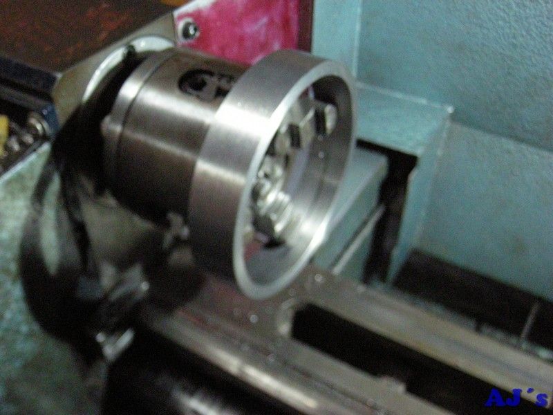
For the large pulley that goes on the engine I went for a fabricated design. Got a lump of steel from a local engineering firm, seems to be part of a large taper lock bush.
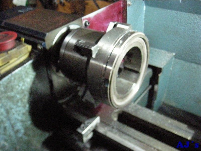
After dialing it in on the 4 jaw, it was hack sawed to size.
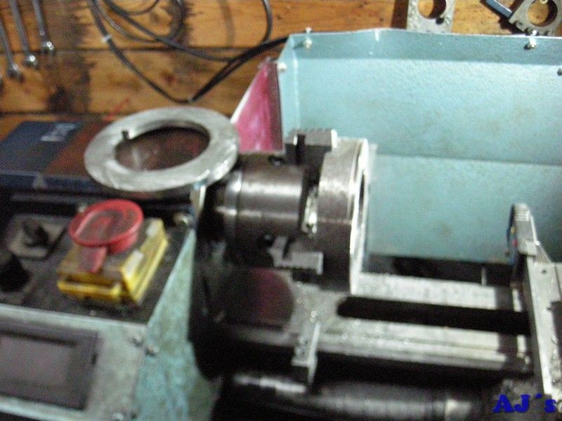
It was faced close to size and the inside bored to size, leaving a shoulder to locate the spoke part for soldering.
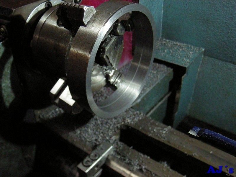
Flipped around add gripped on the inside, it was carefully dialed in.
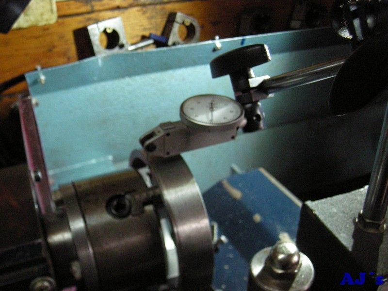
The outside and other face were then machined, leaving it a little over size for cleanup after soldering.
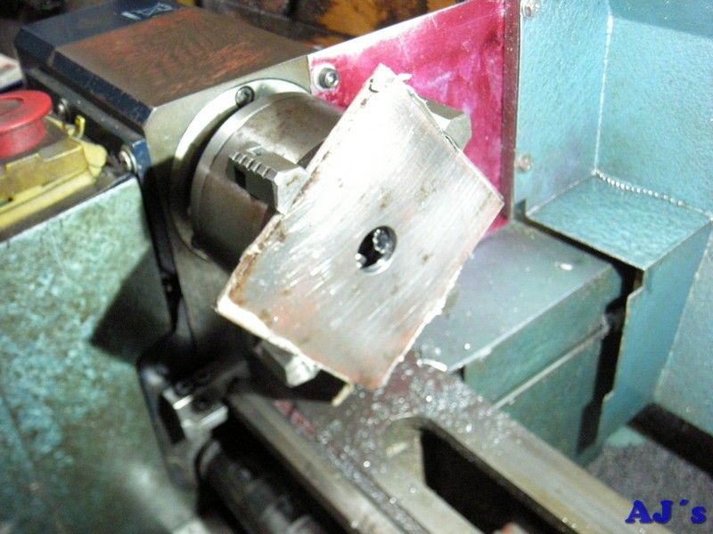
A piece of 3mm plate was centered in the 4 jaw to a centre punch mark.
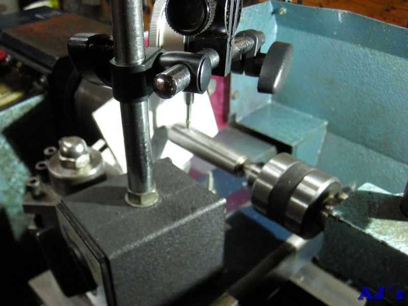
A hole was drilled and bored to fit on the hub.
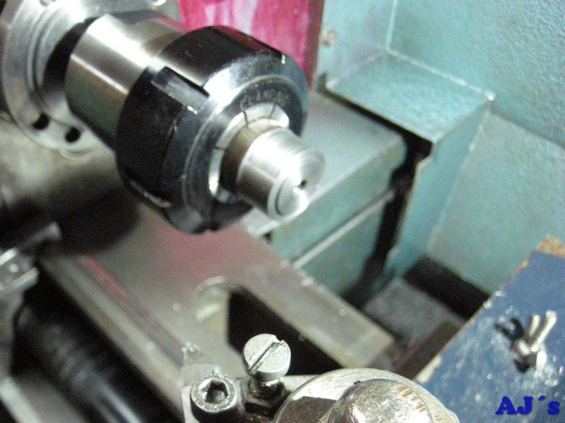
One side of the hub was turned with a register to locate in the plate. It was temporarily drilled and tappet.
After cutting down the corners of the plate it was mounted on the hub.
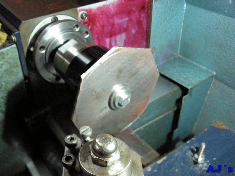
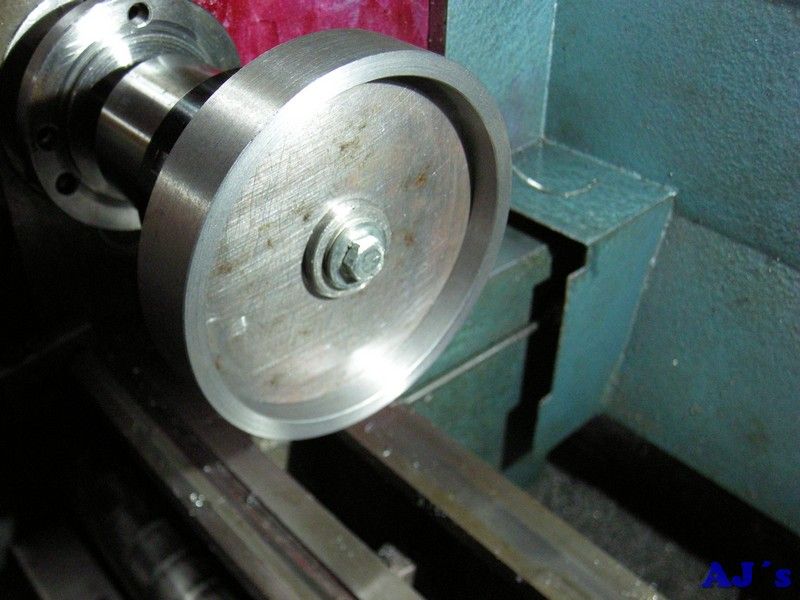
The plate was turned down to a nice snug fit inside the rim.
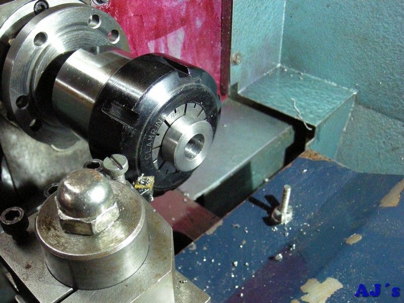
The hub was then bored out for the shaft, parted off, turned around and the end faced. A second hub was also made.
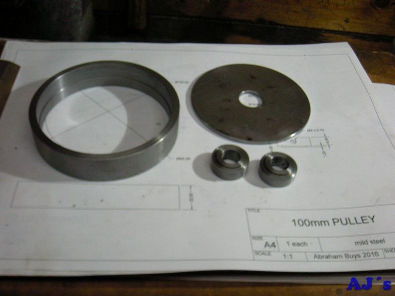
The parts so far.
One of the hubs and the plate was mounted on the rotary table and centered under the spindle.
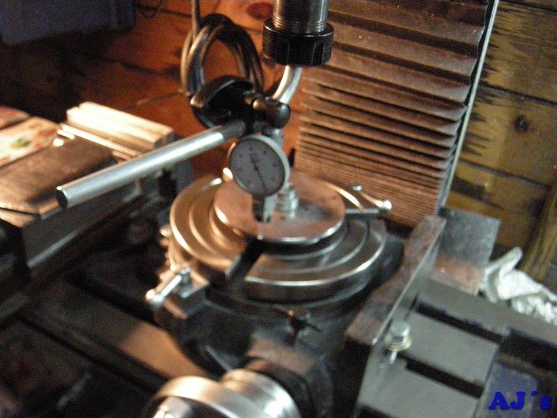
The cutouts to form the spokes were chain drilled.
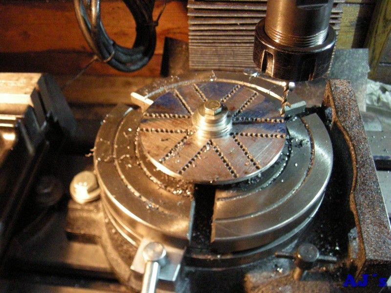
After removing the cut out material all the sides were milled to size. Done very slowly as the outer ends were unsupported.
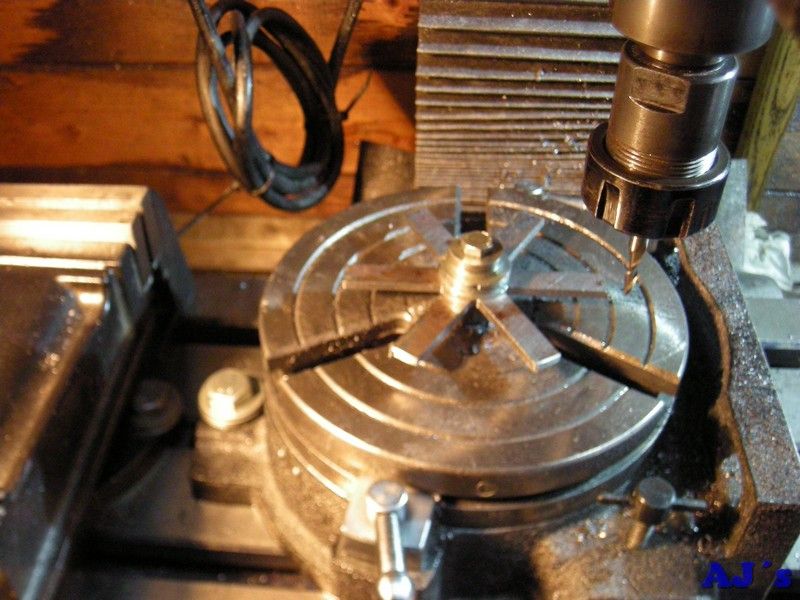
All the parts.
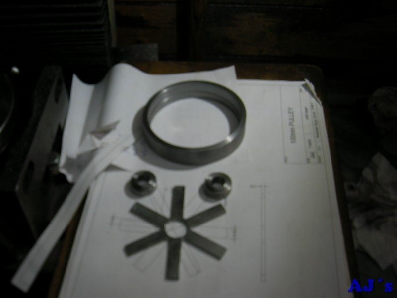
All the bits were brazed together.
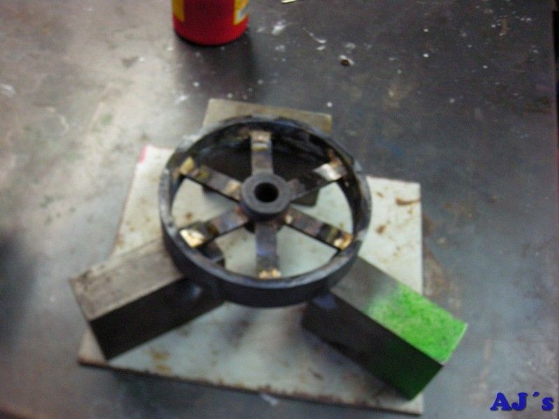
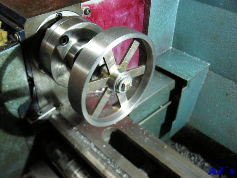
The pulley was mounted on a mandrel and all the surfaces turned to final size. The shoulder left to locate the spokes was also removed.
Fitted on the engine.
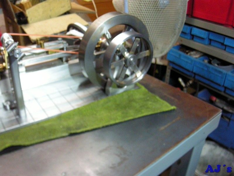
Made a temporary drive belt from insulating tape to test the combination.
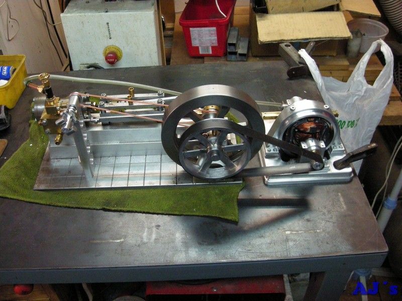
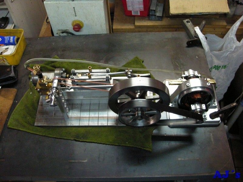
Next will be a base to mount it all.
Cheers.
Abraham