Author Topic: Mill Drill Igaging Dro Install Notes  (Read 22061 times)

Offline ieezitin

  • Hero Member
  • *****
  • Posts: 662
Mill Drill Igaging Dro Install Notes
« on: June 01, 2014, 12:27:54 PM »
Hello lads,

I have suffered for years with manual dials and exotic ways to hang indicators on my machines to get measurements, the procrastinator than I am, I've done hours of research and seen countless people all over the forum world buy these cheap Chinese digi dro's and install them, rate them and so forth  so now it's my turn to jump in.

This will not be concentrated so much on how I install them but more like whats the best way to install them and the challenges that come with free thinking seat of the pants design. Then at the end give an honest report on how they work, which I would like to add my confidence is a little low.

I purchased this pack from Flea-bays for $140.00 incl shipping, which for adding three axis's measurement capabilities to a machine is downright cheap. I have decided to put them on my RF Mill Drill since this machine is used the most in the shop.

Head scratching in the shop I spent a lot of time visualizing these things at work, I then concentrated on fixing the parts to the machine, I focused on the Quill first and my thought was to have the beam fixed and the head slide up the beam, off I go making brackets, drilling and tapping holes, then while I was putting the idea to work and offering up the parts I had made I hit snags, everywhere I looked I saw this idea flawed, it hit screws coming out of the casting and the quill lock arm hit the reader, the protruding wires would be bunching up and flexing, then it dawned on me affix the reader and make the slide move. This realization took 4 hours of trail and error.

So yesterday I realized the quill install would have to be postponed due to a new face plate needs to be made so I started on the table and here's my progress so far.


  I had some aluminum angle handy and decided to hang it on the side rail slot, this takes away the function of using the slide table stops but the benefit of using this real-estate outweighs that function


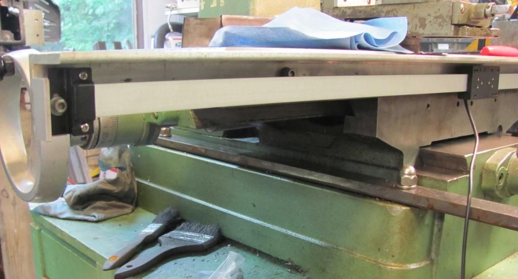
A top shot to give you a general view from a working perspective.


All I did was drill two holes in the angle and affix it by the taper nuts into the slot on the side of the table, then with the hardware supplied I drilled the holes for that, if you notice the top of the angle is not quite flush with the surface plane of the table, that because I used thin parallels to set down the angle elevation but still have it level with it, plus I did not want any work pieces touching that angle surface in case it moved it which might affect the reading of it. The slide elevation was made by inserting a parallel on top of the beam and touching the underneath of the angle at both ends to make it level with the table, all the hardware and holes drilled into the angle were oversized because I wanted this movement for alignment. Now the reader will be static and the slide will travel, no wire movement or bunching, an added bonus of this idea is it will naturally protect the beam and reader from dirt and oil.

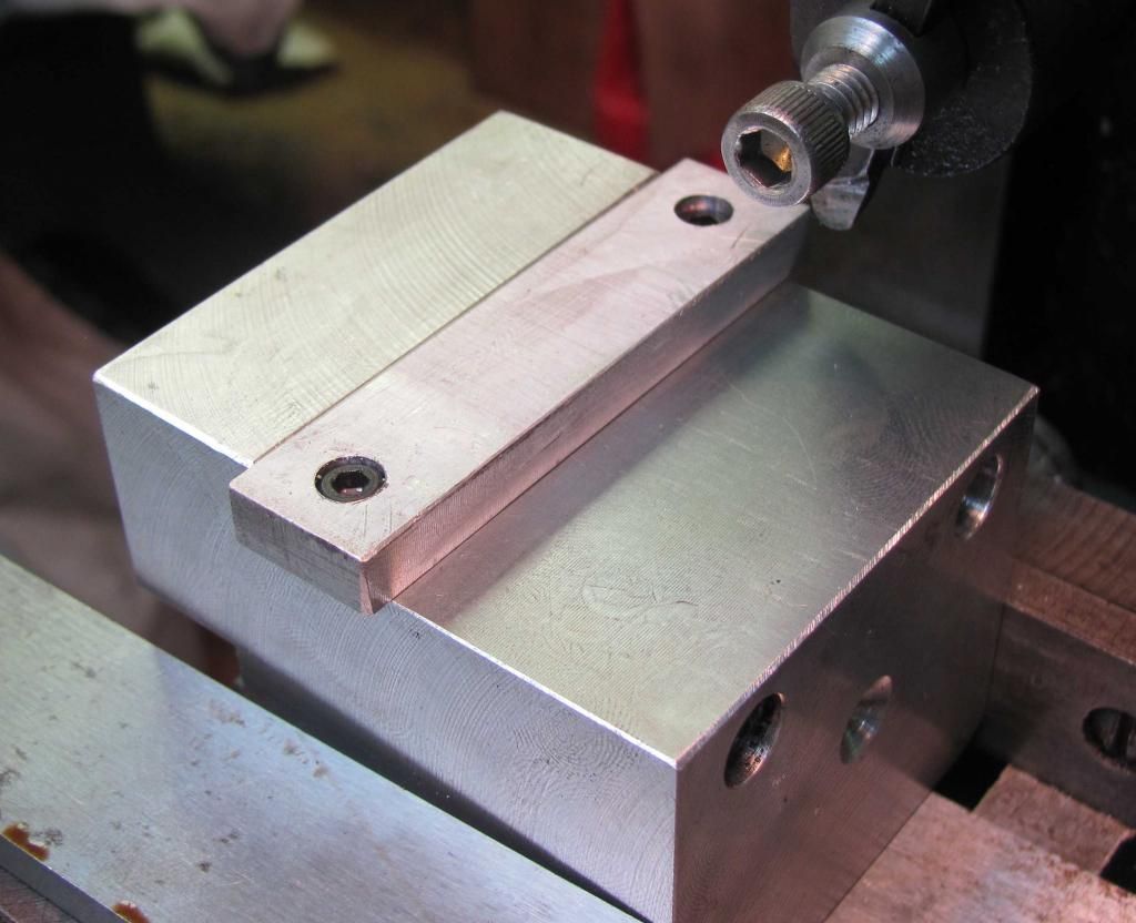
This aluminum block was made to be affixed to the table base and was a mount for indicators and such but now i can use it for the Head reader mount with a little tweaking i can make it work for this job


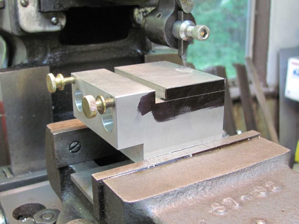
Ready for a little scraping from the shaper to remove some material to lower the elevation so it sits just underneath the Reader Head, There is a slot in it already and i need that to be raised up so i am taking off material and adding later, the pictures will tell the story.


All done and here is the finish.


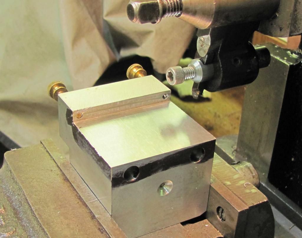
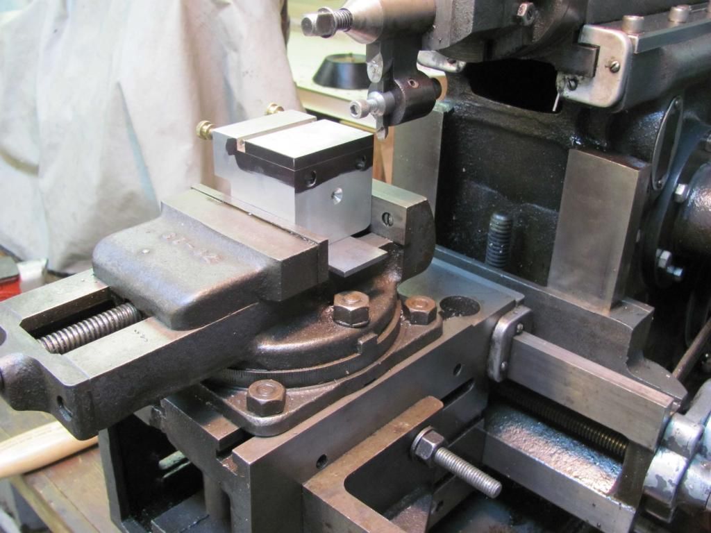
Here is the piece with the added block installed and will be machined to to blend in all contours.


Well thats all i have done so far, i will be back at it soon and show you all the progress.  all ideas and suggestions are welcome.


Thanks for watching..

Anthony.
If you cant fix it, get another hobby.

Offline tom osselton

  • Hero Member
  • *****
  • Posts: 1256
  • Country: ca
Re: Mill Drill Igaging Dro Install Notes
« Reply #1 on: June 01, 2014, 04:59:43 PM »
I have just put a dro on my craftex 601.  I went with the DroPro's 4 axis the x and z went fine but I had to reengineer the quill and y and like you had to make another faceplate for the front. I had enough room to use the existing hole from the sliding scale it came with originally using the same arm that moves with the quill. I have to go to a bbq this afternoon but I will put up some pics tonight.

Offline vtsteam

  • Global Moderator
  • Hero Member
  • *****
  • Posts: 6466
  • Country: us
  • Republic of Vermont
Re: Mill Drill Igaging Dro Install Notes
« Reply #2 on: June 01, 2014, 07:19:29 PM »
I have a round column mill drill, DRO in a box still, and even an Atlas shaper like you (I think) though the last isn't functional yet and lacks that wonderful stock vise. But anyway, following this thread with much interest! :coffee: :coffee: :coffee:
I love it when a Plan B comes together!
Steve
https://www.youtube.com/watch?v=4sDubB0-REg

Offline Jonny

  • Hero Member
  • *****
  • Posts: 780
Re: Mill Drill Igaging Dro Install Notes
« Reply #3 on: June 01, 2014, 07:37:22 PM »
Done similar with overhanging angle on last mill except it was mounted outboard for access to T slots and needed stops.
Coolant and debris will find its way in rest assured. Probably get away with it once but second time scales scrap, had two of mine pack up  when they were dear over 14 years ago.
The dodgy spindle one mounted off a cylindrical collar round quill replacing the original with coolant tap inbuilt. Reader part screwed from rear to an angle and fixed at front right hand side. You will have to make a decent good fitting screw to go in slot in the quill to take up the rotational play.

Are you going to cut the X axis angle and scale down.

Plan that cabling, its flimsy and prone to breaking along with distorting the contacts. Main prob I had was the Warco 3 axis readout draining the SR44 batteries between 3 to 6 days.

Reader brackets that come with these scales are near on usless having compared to dear magnetic, glass and the cheapies all in situ on same axis. Make your own as angle mentioned above and they will be accurate. There can be as much as 0.145mm flex in one direction before the scales starts moving.

Offline ieezitin

  • Hero Member
  • *****
  • Posts: 662
Re: Mill Drill Igaging Dro Install Notes
« Reply #4 on: June 01, 2014, 07:43:20 PM »
Tom..

that would be cool.....  im understanding its the quill feed to be the hardest... not as easy as it looks..

Anthony..
If you cant fix it, get another hobby.

Offline ieezitin

  • Hero Member
  • *****
  • Posts: 662
Re: Mill Drill Igaging Dro Install Notes
« Reply #5 on: June 01, 2014, 08:25:53 PM »
Ah… VTsteam… the shaper is an Atlas and the vise too.. it’s a dream, the key to machining its potential  is the vise on a shaper, its low profile is everything.

Jonny… got ya on the reverse of the angle, I thought about it but went the way I did, I just thought it would be just as easy to make a stop from the horizontal top in the future than to worry about engineering the bracket the other way. I have a feeling the slide or scale will be damaged by dirt and oil but I will remedy this as best I can only time will tell.
I am not going to cut the X axis down I will live with it the way it is. Your right the cabling is flimsy and I am going to protect it with that flexi-shell stuff you can buy at an auto store, the one with a split in it, I realized by doing this the wires need to be protected as best as possible.

The bracket hardware is trash, the holes don’t really meet up and are not sufficient for the job, I am using them just to get going as I can spend time in the future making sturdier brackets, I have found through this install that alignment is key, whoever wants to do this work will need to pay attention to alignment, when the slide and reader move it needs to be  in a straight line and no bowing allowed,  by making my brackets I  allowed movement in the holes so you can position the unit so to limit the distortion while the reader is sliding down the slide rail. The 0.14 thou has been noted, thanks.

More piccies tomorrow  :beer:

Anthony.
If you cant fix it, get another hobby.

Offline tom osselton

  • Hero Member
  • *****
  • Posts: 1256
  • Country: ca
Re: Mill Drill Igaging Dro Install Notes
« Reply #6 on: June 01, 2014, 09:12:06 PM »
Actually the quill wasn't that bad it was the y that seemed harder.

Offline vtsteam

  • Global Moderator
  • Hero Member
  • *****
  • Posts: 6466
  • Country: us
  • Republic of Vermont
Re: Mill Drill Igaging Dro Install Notes
« Reply #7 on: June 01, 2014, 09:32:32 PM »
Ah… VTsteam… the shaper is an Atlas and the vise too.. it’s a dream, the key to machining its potential  is the vise on a shaper, its low profile is everything.

Anthony, I'm going to have to make one. :loco:

So glad I waited to mount the mill DRO. This thread will really help.  :coffee:

 :nrocks:
I love it when a Plan B comes together!
Steve
https://www.youtube.com/watch?v=4sDubB0-REg

Offline tom osselton

  • Hero Member
  • *****
  • Posts: 1256
  • Country: ca
Re: Mill Drill Igaging Dro Install Notes
« Reply #8 on: June 02, 2014, 08:26:30 AM »
Tom..

that would be cool.....  im understanding its the quill feed to be the hardest... not as easy as it looks..

Anthony..

Well this is the original face and the slide it came with

As you can see there is lots of room under the cover I milled a slot for the sliding bar that fit in the existing hole for the previous scale keeping it as long as possible to make sure there was enough in the down position.


I fitted a plate using the existing holes and cut out the center portion leaving maybe 1/8 inch overhang for support although it doesn't touch, the screws are counterbored so the new faceplate will lay flat.


This shows the riser from the slide and the new faceplate as you can see there is no screws holding the scale I can thank " DroPro's " for that, when fitting everything together use 3m outdoor doublesided tape it works great and saves a lot of time 1" on each end holds great.


And a shot put together there was only one problem here, when I put the crossbar in place it sloped inward, I never thought to check the slide bar to see if it was parallel with the faceplate so the riser was removed and was ground to fit with my new grinder  :D all that remains to do now is paint and mount the scale.


I got this a couple months ago thinking mill bit sharpening


 All in all it wasn't that bad a build.

Offline Arbalist

  • Hero Member
  • *****
  • Posts: 673
  • Country: gb
Re: Mill Drill Igaging Dro Install Notes
« Reply #9 on: June 02, 2014, 10:54:54 AM »
I can't square the circle with DRO's for my VMC.  :(  I don't want to loose the stops but fitting the scales at the back looses a little travel. Glass scales are cheap but break easily from what I've heard. Magnetic scales are tough as old boots but cost more and can't be used with cheap read outs. Another thing that irks a bit is that the nice displays can cost nearly £300 and only well, "display"!
I can buy a tablet for a quarter of that price and it does everything bar make the tea ...  :D
I'm sure when something really cheap and easily installed that doesn't eat batteries comes out I'll be the last to know ...  :)

Good luck with the installation. With any luck I'll gain enough information to get into gear myself at some point!

Offline 75Plus

  • Hero Member
  • *****
  • Posts: 624
  • Country: us
Re: Mill Drill Igaging Dro Install Notes
« Reply #10 on: June 02, 2014, 11:05:43 AM »
Anthony, I put Igaging scales on my Grizzly 0704 mill drill a few years back. Like you I found the mounting hardware near useless. Here is the way I solved that problem. Hopefully you may find it useful.

http://madmodder.net/index.php/topic,6512.msg69127.html#msg69127

Joe

Offline ieezitin

  • Hero Member
  • *****
  • Posts: 662
Re: Mill Drill Igaging Dro Install Notes
« Reply #11 on: June 05, 2014, 08:16:16 PM »
75 Pllus....

saw the link and it is a help.thank you.

Notes so far...

don't be afraid to drill into your machinery, its just a piece of metal.

Use aluminum for all bracket hardware, its easy to machine, tap, and make look nice, your going to make mistakes and aluminum will be more forgiving.

make all brackets adjustable, alignment is key, when all brackets are made its a nice feature to tweak them all to set all pieces into place, mill slots or file slots into holes of all hardware to achieve this.

Find a datum point for level and square for scales, once this has been achieved all will fall into place.

use 60%-70% pilot drill hole size for tapping, you dont need to be binding up to align your brackets, personally this range should be used all the time plus it saves on snapping taps.

Here are some pics on where I am with this install.   


the space i desired between the rail and the reader.


this is the close tolerance i have applied to keep it compact.


how i made the back bracket..


and this tool is worth its weight in gold......if you dont have one get one. a tapping stand...


If you cant fix it, get another hobby.

Offline ieezitin

  • Hero Member
  • *****
  • Posts: 662
Re: Mill Drill Igaging Dro Install Notes
« Reply #12 on: June 06, 2014, 05:13:02 PM »
Here we are so far.

I have noticed some slight bowing to the rails and i am wondering if this will turn out to be an issue only time is going to tell and i figure when i start to use this for the first time i will pay close attention to my measurements I will be getting, i may just apply an indicator and have some reference to what happens.

dust and dirt have been playing on my mind and through reading other peoples posts and builds i am going take advice and will cover all the rails with a stainless shields which will have end caps on.

my quill face plate has been made and i will be installing that this week end, its elaborate and fancy but should do the job, i have modified my quill too, i have yet to see another approach on this machine like on how i will be doing it piccies will come for sure.

alright then my progress so far....


i have kept the tolerances tight.


side shot...


My spacer to keep the rail parallel, the flat bar is very close with being parallel with the table so i am using this as a datum point.... we shall see


making sure there is no interference....


Be back later..

Thanks for looking...........  Anthony.
If you cant fix it, get another hobby.

Offline ieezitin

  • Hero Member
  • *****
  • Posts: 662
Re: Mill Drill Igaging Dro Install Notes
« Reply #13 on: June 06, 2014, 08:01:36 PM »
The quill needs looking at. on this machine it has a slight twist or rotation because of slack in the headstock, it annoying to say the least but the Chinese in there wisdom made it the way kay=sera. I eliminated as it much as i could by using the existing depth gage rod hole and slipping in a brass bushing with a nice bearing bushing to suck up the slack, the rail i used it a length of 1/2'' stainless instrument tubing which is dead on size OD so tolerances can be held.

even though i just started to do this build i installed the quill rail two months before, its starting to get oil dry marks on it which tells me its still out, very hard problem to over come!!!...


the bearing fix in the heastock..


close up of the headstock bushing design..


here is the plate i have made to cover the quill headstock that will allow me to have a bracket directly mounted to the rail to aid the z axis ..


thanks for looking..  anthony
If you cant fix it, get another hobby.

Offline ieezitin

  • Hero Member
  • *****
  • Posts: 662
Re: Mill Drill Igaging Dro Install Notes
« Reply #14 on: June 08, 2014, 08:17:04 PM »
well... i only got a little done this weekend, i concentrated on the quill face plate. I made it out of 16 gage stainless which is balls hard to drill trough, im stupid really i always revert to stainless because i like the look and feel but curse every time i have to machine it.

this is going to end up as a bracket support for the rail on the quill, all brackets will be made to make sure all is in line with the rail.

here is the view..


front view where the brackets will be installed.


Not far away now from having a dro system on the mill, im very much looking forward to it..

All the best..

Anthony.
If you cant fix it, get another hobby.

Offline vtsteam

  • Global Moderator
  • Hero Member
  • *****
  • Posts: 6466
  • Country: us
  • Republic of Vermont
Re: Mill Drill Igaging Dro Install Notes
« Reply #15 on: June 08, 2014, 08:50:57 PM »
That cover was nicely made! Clean sheet metal work -- dresses up the mill, in my opinion,  :thumbup:
I love it when a Plan B comes together!
Steve
https://www.youtube.com/watch?v=4sDubB0-REg

Offline Jonny

  • Hero Member
  • *****
  • Posts: 780
Re: Mill Drill Igaging Dro Install Notes
« Reply #16 on: June 10, 2014, 02:45:00 PM »
The quill needs looking at. on this machine it has a slight twist or rotation because of slack in the headstock

They all do and what I said earlier with the grub screw riding in the slot.

Is the brass a new depth stop or mounting for scale, if so you always have movement. Far better off the bottom aluminium quill plate.

Offline ieezitin

  • Hero Member
  • *****
  • Posts: 662
Re: Mill Drill Igaging Dro Install Notes
« Reply #17 on: June 10, 2014, 07:15:20 PM »
VTSteam

Thank you for the compliment..

Jonny..

not sure where the set screw is any pointers..... and what do you mean with better off the bottom aluminium quill plate?

Note: the pdf file containing the manual for the machine is a little useless.. :(

Thanks..

Anthony.
If you cant fix it, get another hobby.

Offline ieezitin

  • Hero Member
  • *****
  • Posts: 662
Re: Mill Drill Igaging Dro Install Notes
« Reply #18 on: June 17, 2014, 07:46:21 PM »
Well....

I got started on the Quill install, my attachment that's sitting on the stainless rod, when it gets to the bottom it interferes with the head casting so i had to mill off the corners for it to seat right, could have filed it but decided to get the shaper into action.


After i milled the edges down here it is protruding through the face plate, its all free from touching the face plate and the internal casting.


next was to install the fixing hardware for the bracket that holds the scale, i could have welded nuts through on the back but i took a chance on tapping the 16 gage stainless 8-32 and installing a thumb screw with lock washer and washer from the back for the thread to accept an knurled head nut to lock it down from the front. It worked.


Next was to install what i have, this done i drilled and slotted the aluminium angle with the positioning of the scale to be flexible,  i tight drilled the top screw and the lower milled a slot so i could swing the bracket over to align it parallel to the quill moving up and down,


this all done i stuck an indicator to check for parallel. Results were .002 over 6'' distance.


All well that ends well.

I still think a " hard rain is gonna fall "..

Thanks.

Anthony.
 
If you cant fix it, get another hobby.

Offline Noitoen

  • Full Member
  • ***
  • Posts: 143
  • Country: pt
Re: Mill Drill Igaging Dro Install Notes
« Reply #19 on: June 18, 2014, 03:26:38 AM »
Hi,

I've installed the same scales to my mill and was a huge help in the machining process. One thing I found that, sometimes, randomly, the scales would reset their values due to electrical noise. One big culprit would be my fluorescent work lamp on/off switch.
I upgraded the system to the wi-fi android project and the problem would persist. I then replaced the cables with a 4 core individual screened cable, soldered directly to the scales pcb (there are pads for this purpose), shielded the scale's plastic box with some aluminium tape and now they work fine. 

Offline Arnak

  • Jr. Member
  • **
  • Posts: 30
Re: Mill Drill Igaging Dro Install Notes
« Reply #20 on: June 18, 2014, 08:43:27 AM »
Hi Folks,

Just a quick question regarding scales.

I noticed that the slide is just a plain aluminium bar, so how does the read head know where it is to get the readout?

I can't seem to find an explanation on how the read heads actually work. :coffee:

Martin

Offline 75Plus

  • Hero Member
  • *****
  • Posts: 624
  • Country: us
Re: Mill Drill Igaging Dro Install Notes
« Reply #21 on: June 18, 2014, 09:13:07 AM »
Hi Folks,

Just a quick question regarding scales.

I noticed that the slide is just a plain aluminium bar, so how does the read head know where it is to get the readout?

I can't seem to find an explanation on how the read heads actually work. :coffee:

Martin

Martin, that aluminum bar is actually a "U" channel. The encoding information is imbedded in the channel which is on the reverse side.

I believe Anthony has set a record for the number of pictures of scales without once showing the back side of one!!  :clap:

This thread shows the encoder side of the scales.  http://madmodder.net/index.php/topic,6512.msg69127.html#msg69127

Joe

Offline Arnak

  • Jr. Member
  • **
  • Posts: 30
Re: Mill Drill Igaging Dro Install Notes
« Reply #22 on: June 18, 2014, 02:17:04 PM »
Hi Joe,

I see now, I thought I was missing something there. :doh:

The mill looks identical to my Warco Major so it gives me a good idea how to fit a DRO to mine.

Thanks,

Martin

Offline ieezitin

  • Hero Member
  • *****
  • Posts: 662
Re: Mill Drill Igaging Dro Install Notes
« Reply #23 on: June 18, 2014, 05:54:51 PM »
Noitoen.

great information, that will narrow down that problem if it occurs. I too purchased a Tablet about 3 months ago with the intent of using it as the display, i saw the build Yuri did, in fact that was the inspiration for me to do the I-Gaging system. Please all information on setting up the code and or app for the Android tablet i would welcome.

75....

HA ha ...... I am glad its been  pointed it out and you're right!. It never ceases to amaze me how people see problems differently and over come challenges individually. I read your thread on your build and i noticed yours were facing out..... it works.. i just never thought to mention it.

If i need to cut these scales down is there any problem i should be aware of?


Anthony.
If you cant fix it, get another hobby.

Offline 75Plus

  • Hero Member
  • *****
  • Posts: 624
  • Country: us
Re: Mill Drill Igaging Dro Install Notes
« Reply #24 on: June 19, 2014, 10:12:55 AM »
Anthony, cutting the scales down does not effect the readings. Even flipping the scale over, end for end, does not seem to cause any problems either.

Joe
« Last Edit: June 20, 2014, 08:59:19 AM by 75Plus »

Offline vtsteam

  • Global Moderator
  • Hero Member
  • *****
  • Posts: 6466
  • Country: us
  • Republic of Vermont
Re: Mill Drill Igaging Dro Install Notes
« Reply #25 on: June 19, 2014, 09:12:28 PM »
And I'm still following this -- very nice looking work, Anthony.

Do I see an Atlas horizontal mill, in addition to the shaper?
I love it when a Plan B comes together!
Steve
https://www.youtube.com/watch?v=4sDubB0-REg

Offline ieezitin

  • Hero Member
  • *****
  • Posts: 662
Re: Mill Drill Igaging Dro Install Notes
« Reply #26 on: June 20, 2014, 05:05:46 PM »
VTsteam..

Yes its an Atlas horizontal, its a basket case..the original power transmission has been converted to a timing belt drive, so no change over on speeds, no table drive (knuckle PTO) and the motor has fried.

I purchased it for a project but my heart fell out of it.... I think the horizontal design is really valuable, Hobbing, keywaying and such, and the word on the street for model makers this is the power house of small machine tools, ive used it but not much.....

Alas one day the hammer is coming down and will be parted out, or sold whole for a reasonable fee.

Anthony.
If you cant fix it, get another hobby.

Offline vtsteam

  • Global Moderator
  • Hero Member
  • *****
  • Posts: 6466
  • Country: us
  • Republic of Vermont
Re: Mill Drill Igaging Dro Install Notes
« Reply #27 on: June 20, 2014, 10:19:33 PM »
I have an Atlas H Mill, too, though missing the table drive -- otherwise in fine shape.

I seem to have, not by intention, a nearly complete Atlas shop -- Craftsman 12" Lathe (Atlas made), Atlas shaper, and the Atlas horizontal mill. When I bought the lathe, the seller even threw in a small Atlas screw press as a bonus.

And like you also have the Asian round column mill drill (mine is branded Enco) and the same DRO's (unmounted yet). I'm waiting to see how yours turns out before starting to add mine. And I really want to get the shaper working by this summer. I think I'm just missing a gear in the table advance for that. Keep up the good work!
I love it when a Plan B comes together!
Steve
https://www.youtube.com/watch?v=4sDubB0-REg

Offline ieezitin

  • Hero Member
  • *****
  • Posts: 662
Re: Mill Drill Igaging Dro Install Notes
« Reply #28 on: June 29, 2014, 08:28:13 PM »
well.... i have completed the install. the z axis was by far the most complicated. The slide bar i installed worked, its runout is about .005 overall length both ways, the bushing i put into the quill plate holds the tolerance for what this set up can handle, granted i have not used it allot yet, but i have run it up and down at least 40 times, also milled a slot to depth and it showed dead on, saying that it may gradually loose tolerance.

Here is the bracket from the slide rod.


Here it is installed.


All i have to do now is make a cover plate for it.


It from the picture dont look square but it is.


If anyone is going to do this install make sure all your fixture holes can be tweaked, slots and wide hole clearance are a must, all fasteners can have washers which will take up the width. My Bushing arrangement worked, the key was the straight piece of instrumentation tubing i used, a straight piece of drill rod will do the same, there is slight play but the closer it gets to the bushing it closes in. My tolerances on the rod are less than .005 on both directions.

I will use this set up for a while and report what  find, all in all i am happy with it.

Anthony.   


If you cant fix it, get another hobby.