Thank you John and David.
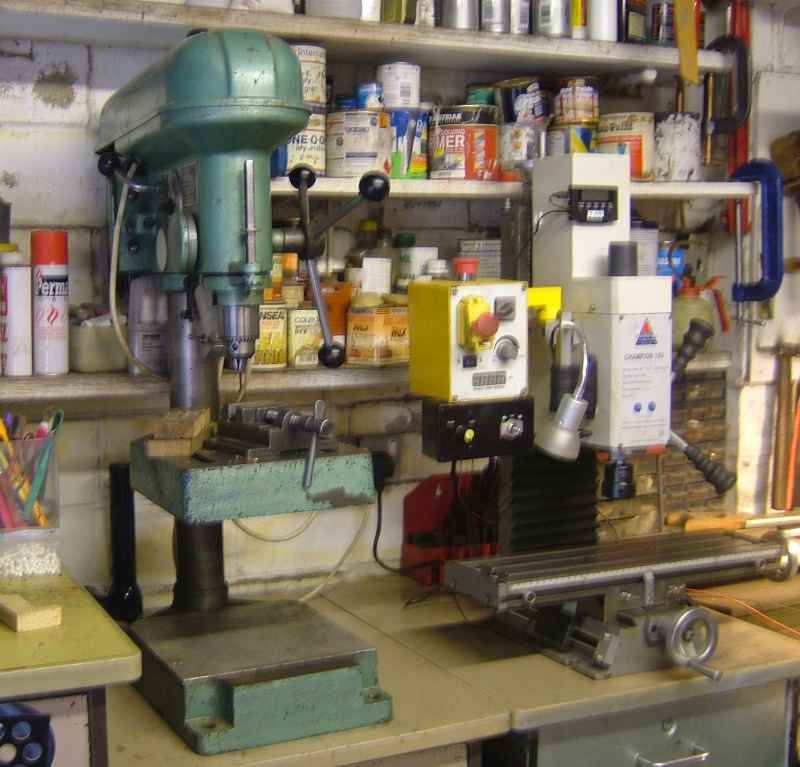
One of the major causes of delay after buying the mill and before I could use it was finding somewhere to put it. After moving some stuff around this is what I came up with.
 Mini Mill Modifications
Before I got the mill, the drill was on the right but if I had put the mill on the left then the table couldn’t move to the left because of the cabinet there, and it couldn’t move to the right because the handwheel fouled the base of the drill. So the drill had to be moved as well. That meant one of the shelves had to be moved too.

Then I discovered that the x axis power feed (not shown) fouled the base of the drill. I considered raising the mill so it would go over the base of the drill, but that still wouldn’t give full x axis travel because it would foul the column of the drill. I could have had the mill overhang the end of the workbench but the workbench is quite full enough already. I decided that I would have to alter the power feed.
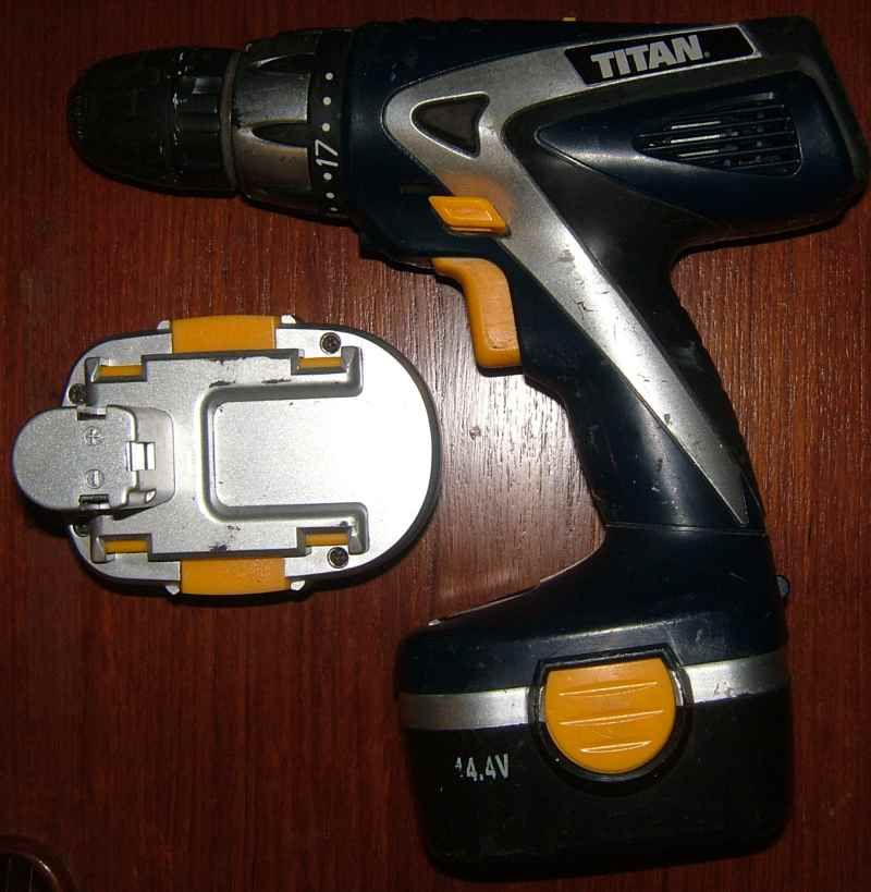
After some research on the internet I decided to try and do it using an old cordless drill. Unfortunately I didn’t have one, so I bought one off ebay for £3.50. It was local so there was no post to pay and the seller even dropped it in for me.
 Mini Mill Modifications
When I had a look at it I decided it was far too good to break up for the motor even though there was no charger. I charged it using another charger and some leads with croc clips and the batteries hold charge better than the cordless drill I’ve been using.
I put a wanted ad on freecycle and was offered a 14.4V drill within an hour, which I picked up the following morning. I tried it with a 12V power supply and a socket to fit the x axis handwheel and it would move the table to and fro quite happily and quite fast enough drawing about 2.5A on starting. That meant that I could use the existing 3A controller.
The drill also provided a suitable contact clip for me to use for charging the batteries for my ebay drill – fastening it to an L shaped piece of plastic prevents it from being connected incorrectly.
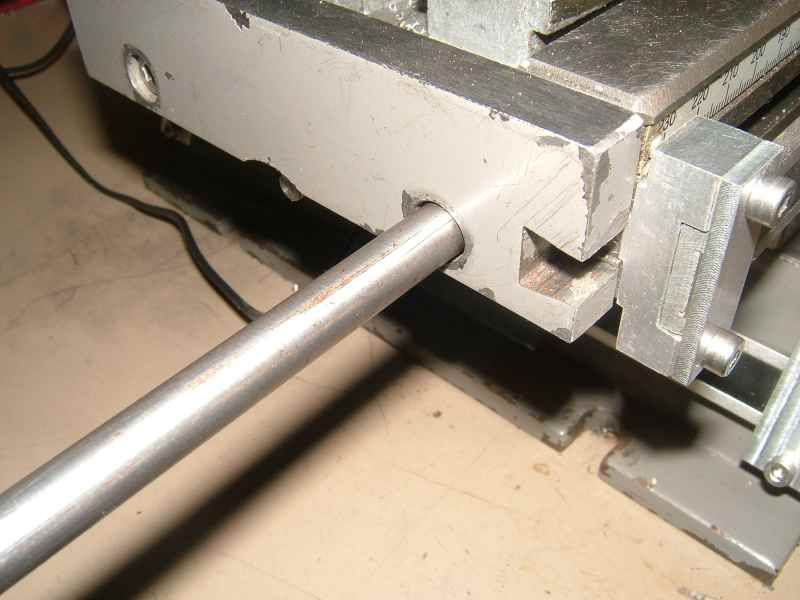
I took the drill to pieces and the motor looked like it would be perfect for the job. All I had to do was work out how to fasten it on. I decided to screw a couple of rods into the end of the table to hang it on – that’s what most people seem to do.
I tried a couple of 3/8 rods but discovered that these weren’t very parallel, and weren’t very consistently non parallel either.
 Mini Mill Modifications
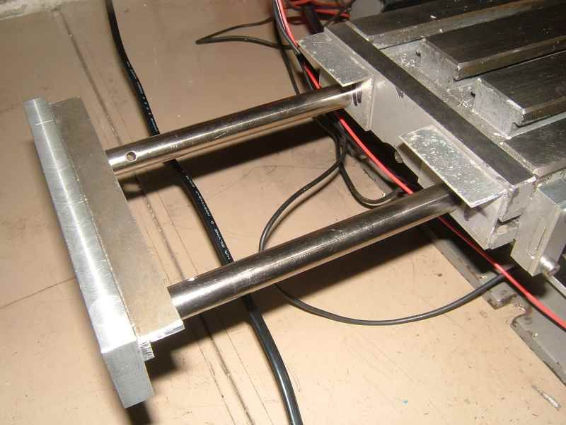
I could have added a couple of washers to make them seat on the flat surface rather than the counterbore but decided to use a cut up half inch rod from an old printer.
 Mini Mill Modifications
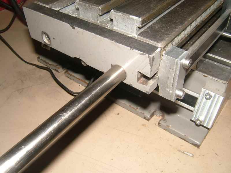
The half inch rods were consistently less than 0.15mm off parallel when I tried them and by fastening a plate to the outboard ends I could get them to stay parallel. The plate was salvaged from the previous power feed.
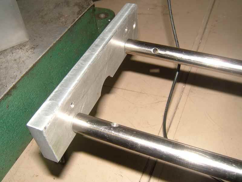 Mini Mill Modifications
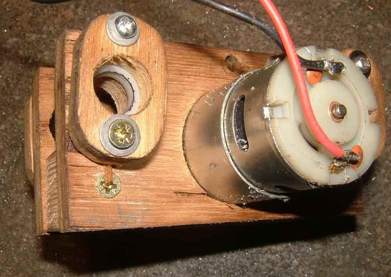
The motor mount was designed by empirical evolution.

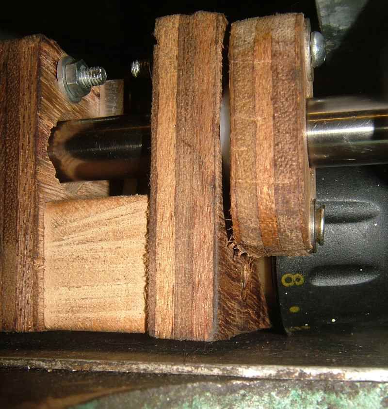
I used plywood because I wasn’t sure it was going to work and so I wouldn’t have wasted any expensive materials. I cut a couple of holes in two pieces of plywood using a hole saw and opened them out using a small sanding drum so that I could fit one on each end of the motor. They were then fastened to a block of wood and I drilled some oversize holes so I could adjust the position of the sliding bearings. A small piece of alloy was screwed on to locate the tab on the gearbox which takes the torque reaction in the drill. This also shows my failure to plan ahead as I had to drill a hole in it later.

 Mini Mill Modifications
Four delrin bearings were mounted in blocks of wood and fastened using oversize holes for adjustment.
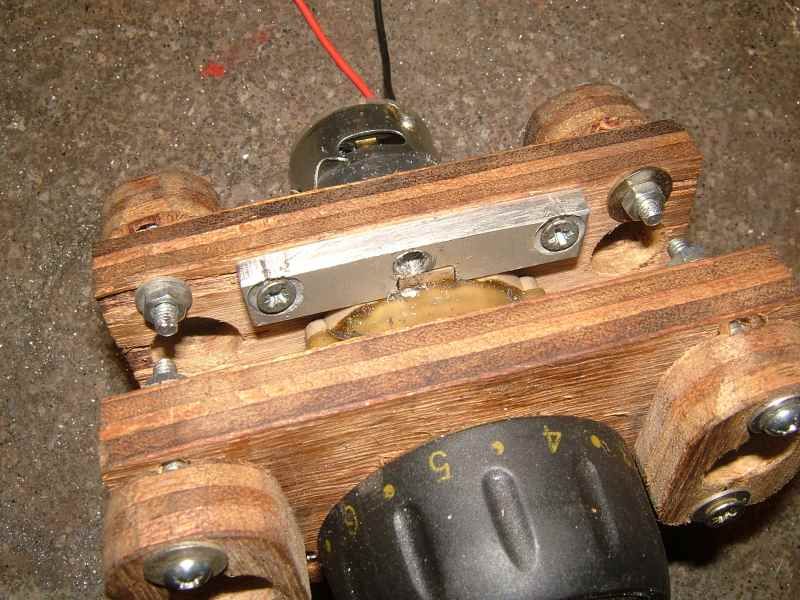
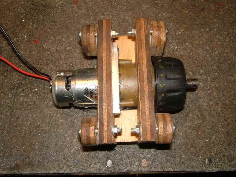
 Mini Mill Modifications
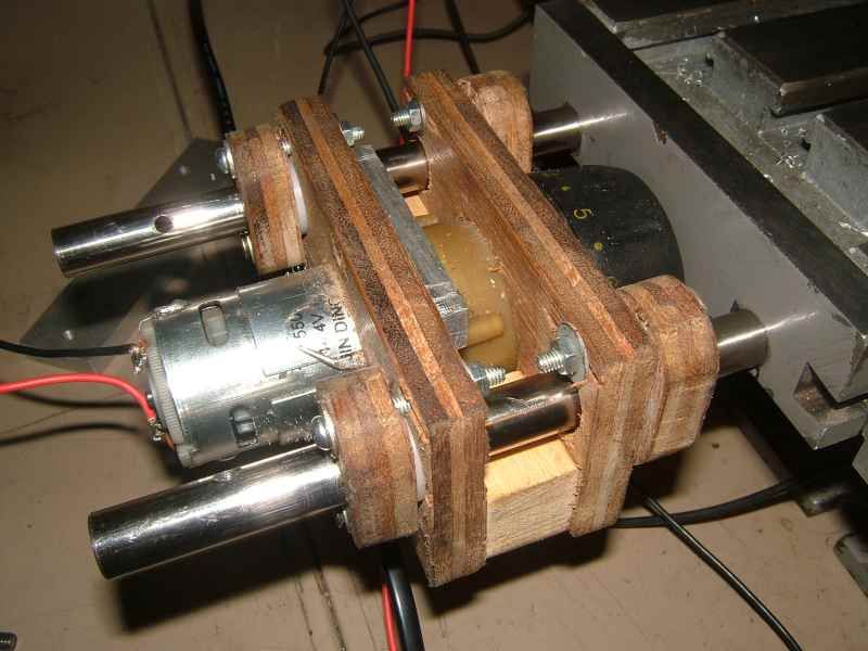
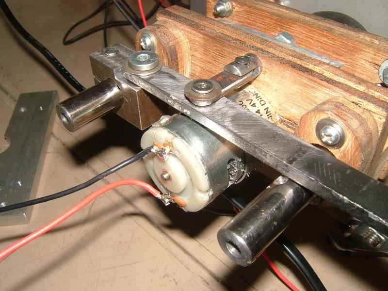
This is what the assembly looks like.
 Mini Mill Modifications
To get it to drive the table I drilled the thread out of the spindle and cut a notch in the end.
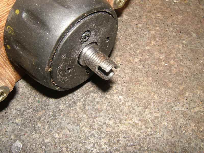 Mini Mill Modifications
I had hoped that the existing hole in the spindle would be enough to guide the drill but it wasn’t and the hole ran well off true, so I dismantled the drill motor's gearbox and put the spindle in the lathe to bore it true. I made a short adapter piece to fit in the existing hole in the end of the x axis feed screw and fastened it with a 2mm roll pin salvaged from a printer. A second pin from a printer provided the cross piece to engage with the dog on the drill motor.
 Mini Mill Modifications
I spent some time adjusting the feedscrew to run true. Removing the dowels holding the end plate to the other end of the table allowed me to move the handwheel bearings enough to get the left hand end running reasonably true over the whole travel of the table. I also tried reversing the table nut – which did make difference – it made it worse.
 Mini Mill Modifications
First tests with the motor on the mounts were successful and the motor could be slid in and out of engagement easily.
 Mini Mill Modifications
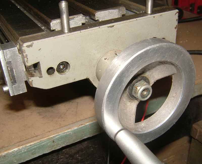
A clamp on the rear bar stops the motor spindle from completely disengaging from the feedscrew extension but allows the dog to disengage and provides a convenient point to mount an operating lever. I had a little trouble

getting the lever and operating links at the right levels, which explains the corner milled off the clamp and the use of the thinnest washers I could find.
 Mini Mill Modifications
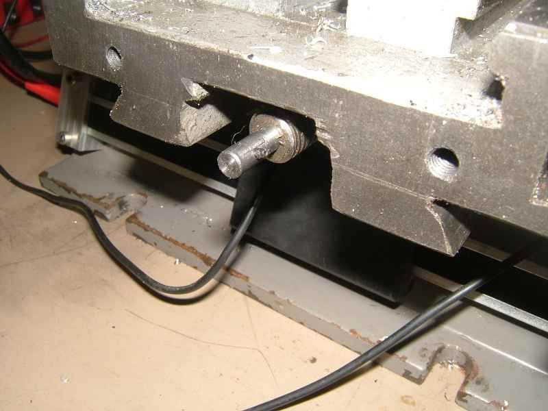
A test at this stage shows that the table will traverse quite happily over the drill base, although there is no detectable clearance. However I could make some clearance here with a chip tray under the mill, or taking away the aluminium plate which stops the drill base filling with rubbish.
 Mini Mill Modifications
Next were some mounting brackets for a cover. The left hand cover mount was a bit of aluminium angle from the scrap pile. The right hand bits also came from the scrap pile and were a handily shaped bit of extrusion from a greenhouse which has a lip on the bottom edge to keep them square.
 Mini Mill Modifications
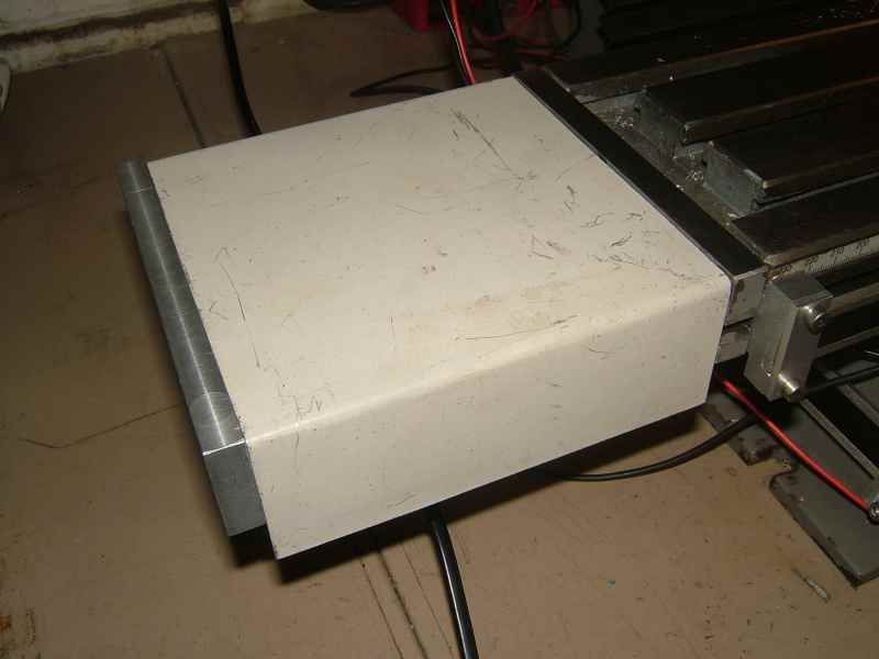
The cover was made from an old computer case.
 Mini Mill Modifications
I am still undecided about how to finish the cover off.
It needs a slot for the operating lever and I think it looks wrong hanging down below the end plates. However if I shorten it to the same level as the bottom of the end plates then that ugly plywood becomes visible.
There'll be more when I've done it.

Russell


