I was at this again recently and took some pictures while working on things. I was thinking "hey, I should post a short writeup on this" but then it occurred that I already started a thread on it! Wow, memory don't fail me now!
So I ended off last time saying that I spent a lot of time working on the blade guides and I might have some pictures....
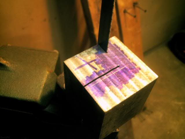
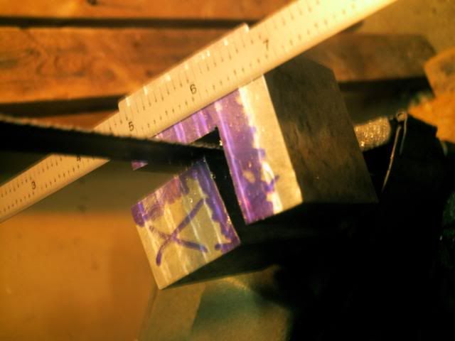
At last, here we go:Rough cutting just shy of the layout lines. Safety here might be a tad questionable, but I had my hands braced in such a way that I was unlikely to slip into the blade. The chunk of steel gets hot while doing this, but DO NOT FOR ANY REASON WEAR GLOVES AT THE SAW! I swapped between the two I was making once one got too hot to handle. Especially with most of our small machines, I have learned to value my bandsaw over any other tool to save time in removing large amounts of waste material. In this case, I even still have the chunks that were cut away for another project some other day!
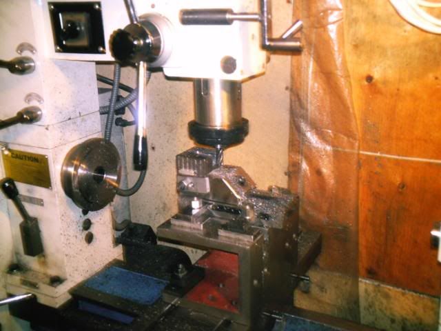
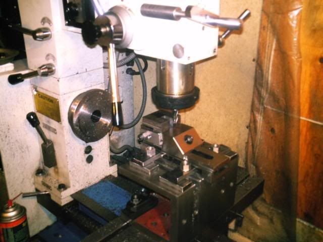
Pictures of the milling operations weren't great, as I was spending all of my time thinking and cranking. Most of the cutting was done at very shallow depth and slow feed due to my machine & setup's complete lack of rigidity.
Back to the bandsaw to reveal more of the part within!
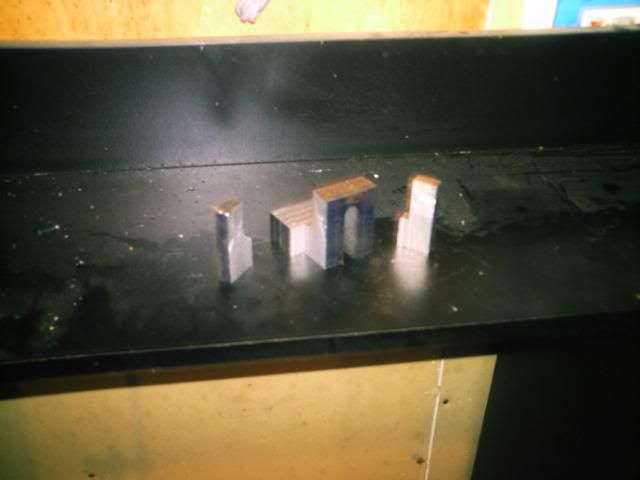
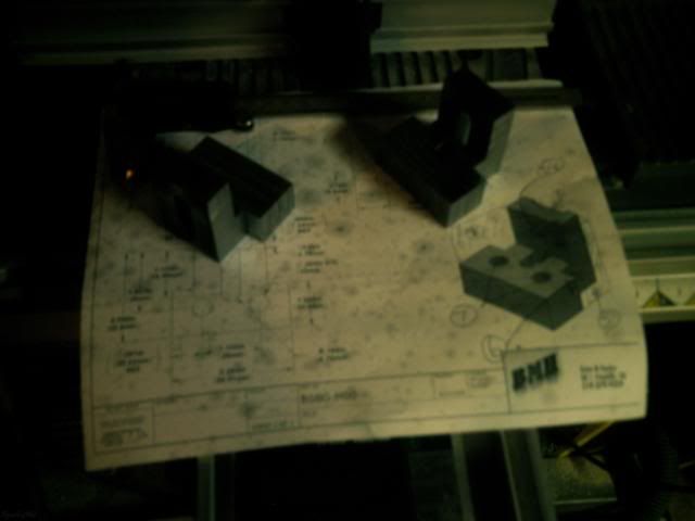
Alas it's starting to look like the CAD model!
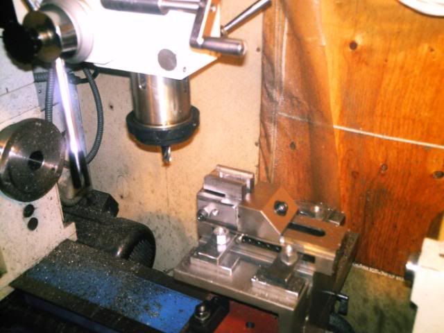
Once again on the mill to cut the groove in the back. The slot for the bolt and guide bearing was cut using two setups.
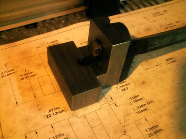
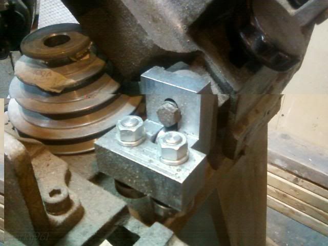
Skipped a few steps and pictures, but here it is mounted on the saw with bearings and all:
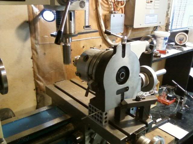
This setup should be looking familiar by now. It's how I use my rotary table most of the time. But there's a bit of a twist this time. I have the rotary table angled down by 5 degrees to account for the lead of the worm gear. I would probably try something a bit more stable next time, but this didn't move despite the single-point hammering away.
It's hard to get it up high enough so that the spindle reaches far enough to cut while keeping everything nice and rigid. Nature of the beast, I suppose... and I grudgingly live with it until I have space/money/time for a better setup.
To help out a bit, I made up a very rigid single point gear cutting tool. It's like a fly cutter but the tool is perpendicular to the spindle - not sure what the name would be.
I hand ground the tool bit using the old gear as a checking gauge. After a bit of stoning we're off to the the races. Material was generously donated by a friend of a friend - some sort of very expensive looking bronze. I had made up the blank and arbour a few months ago and didn't take photos - pretty standard stuff there. ;) I was going to make one out of aluminum too and use it to verify the setup, but that just didn't happen.
Dividing using the rotary table was simple because 20 teeth means all even numbers. I should note too that the first time around I cut to the full depth I thought would be correct. Slow and steady and it cut nicely albeit very noisily.
Skipping ahead a few chapters, I ended up re-mounting this and cutting around the whole thing 2 more times before it fit. Two things I did right, though not on purpose: Don't tear down the setup before checking the part, and when making a difficult one-off part cut small, check fit, cut a bit more, repeat.
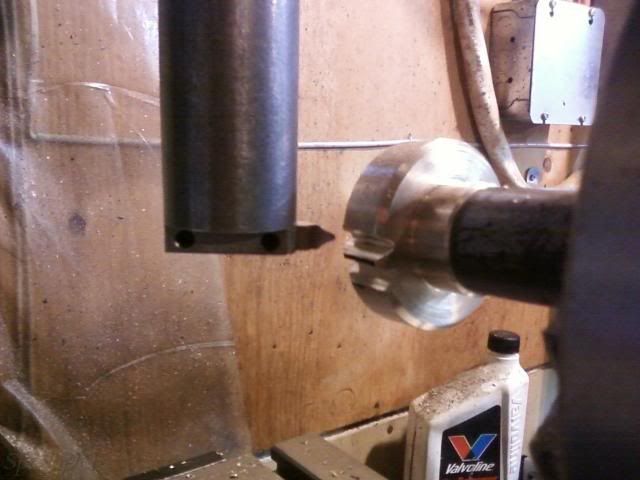
Making the last cut - WOO HOO! (hours passed between the two shots)
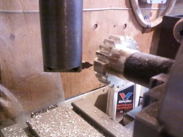
Mostly done, just needs hole cross-drilled for a roll pin and a keyway cut.
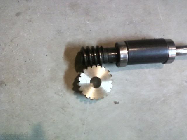
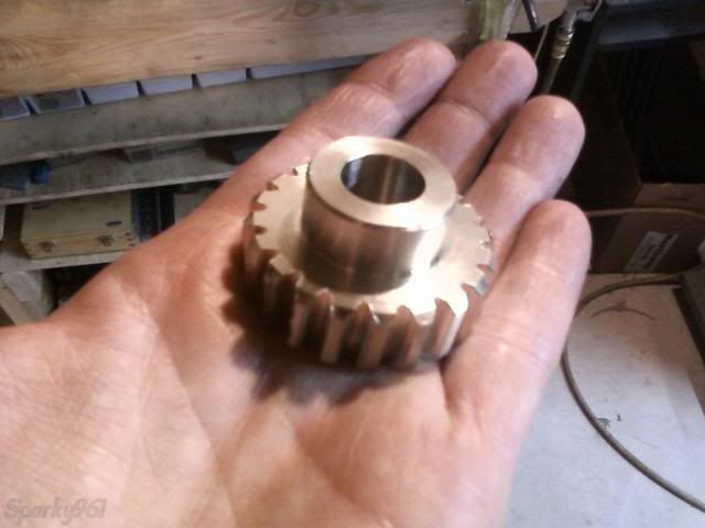
After checking the fit, I found the gears were way too tight. I could turn them by hand with considerable force but after re-cutting them multiple times I was worried it would become too loose if I did another machining pass. So, a bit of thinking and a bit of reckless caution thrown into the wind and I decided to run them in - using something like what may have been in there originally, OIL AND GRIT. Now, generally you don't want to be throwing sand into the running gearbox of any machinery but let me tell you the process worked FANTASTICALLY! I used a haphazard combination of chainsaw oil, 10W30, penetrating fluid, granite dust, and some of the aluminum oxide and silicon carbide dust swept up from around my grinder.
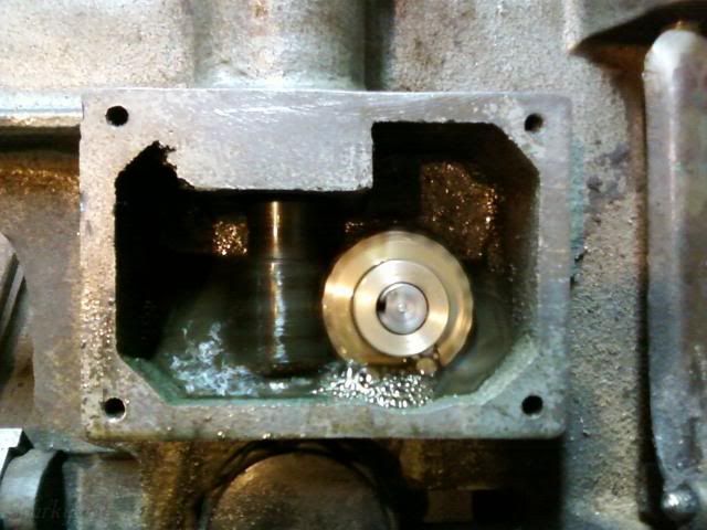
If you saw my thread on the repulsion motor (
http://madmodder.net/index.php?topic=6574.msg70005#msg70005) the next picture might make more sense. Really, I didn't know I had a motor that turned the right way. I just needed to make it turn and it was getting very late! The gears got a bit hot while it was doing it's thing, but they ran in to a nice fit with very little resistance. At this stage the gear is just held on the shaft with a light friction fit. It didn't slip while I did this, otherwise I would have had to put in the keyway and/or roll pin first. Let's just say I was excited to see them turning together.

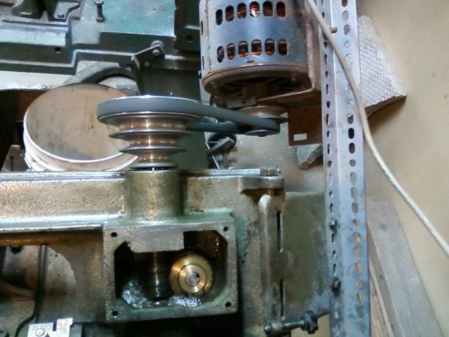
After all of that crazy fun, I did a thorough cleaning and covered the openings with duct tape to keep them clean.
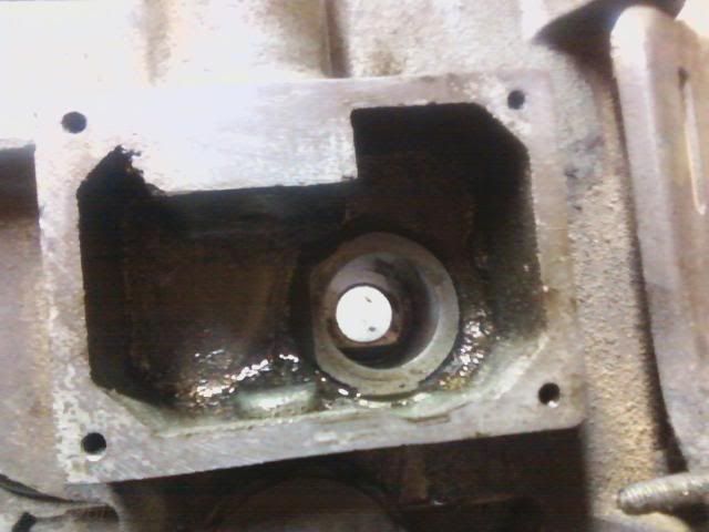
Still left to do is to finish the gear details and then I have some ideas for this mess... If you look carefully, you'll see that someone has broken off the right bearing and replaced it (farmer style) with a nut.
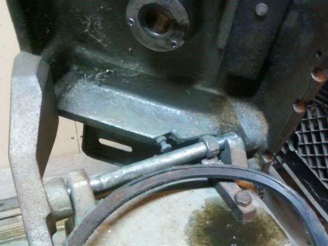
Well, that's all I have for now. We'll see how many months before I update this thread again. Thanks for your interest!
-Sparky