Author Topic: Mill Electrotrickery Part 2 - Drilling into Power feeds  (Read 6270 times)

Offline RodW

  • Full Member
  • ***
  • Posts: 120
  • Country: au
    • Vehicle Modifications Network
Mill Electrotrickery Part 2 - Drilling into Power feeds
« on: May 14, 2013, 01:04:04 AM »
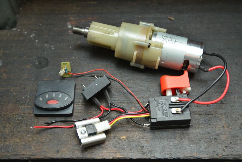
I can't claim credit for the idea but part 2 of my electrotrickery for my Seig SX3 mill is to add a power feed for it. Yes I know, you can buy a power feed attachment for it but my shop is so small, I would not be able to close the door if I used one of them. I was resigned to remain power feedless until I saw an idea that used a cordless drill motor and it just so happened that my Wife's 86 year old mother had won one in a raffle so with the necessary approvals, I broke the brand new seals on the box and stripped it down.


Some people leave the clutch on to protect against running out of travel and I was going to as well until I undid the wrong part of the chuck and ball bearings flew everywhere. Never mind, the Seig has provision for limit switches so it looks like I will be installing some. Most people who have used one of these let them stick out from the end of the table but this is not going to work in my case as once again, I won't be able to close the door.

I thought about using the existing drilll controller and screwing in a bolt that pushed the trigger in as it had quite a range of speed control and did a bit of exploration work.


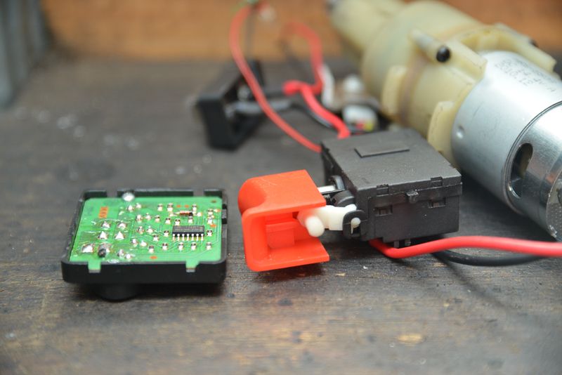
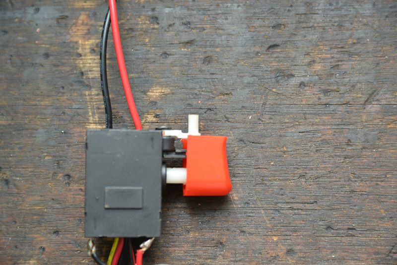
And got as far as cutting the top of the trigger off to gain access to the direction control


So now all I needed to do is to work out how to position the motor behind the mill table so I could shut the door!

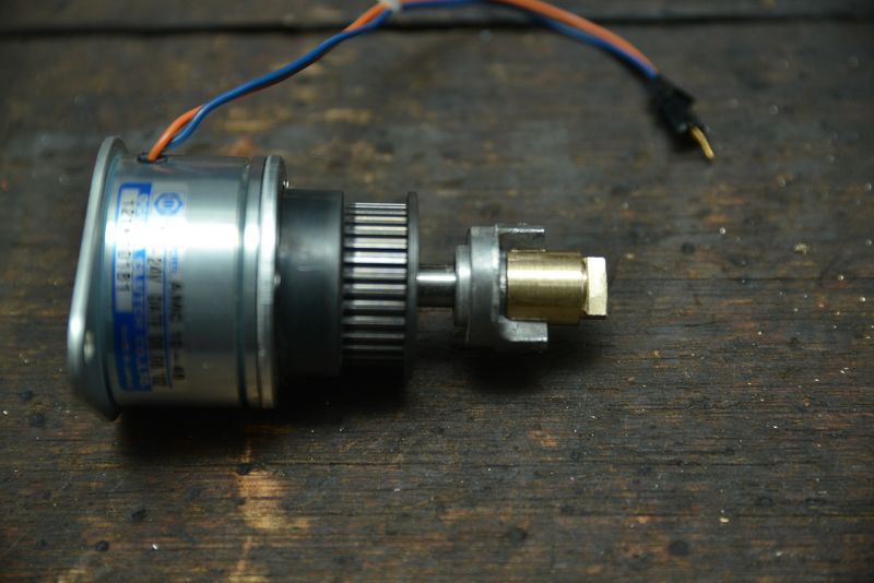
I happened to have an electromagnetic clutch lying around.


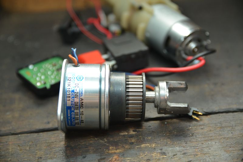
This handy gadget lets the timing belt pulley freewheel until 24 volts is applied to the two wires and an electromagnet cicks in and the shaft is locked to the spindle automagically! So if the power feed is turned off, the power feed will automatically disengage and allow use of the hand wheels.

So the next step was to attach a drive tang to the shaft. I tried to remove the yoke from an old lovejoy coupling on it. It was pinned on with a fine pin I could not remove so I decided to use it to hold the shaft and be done with it.

I don't have that much room, so I trimmed the fingers on the yoke. There was nowhere much to hold it but I came up with a way


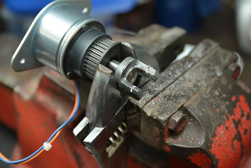
And before long, I had come up with a tanged shaft held on with a roll pin that fits nicely into the end of  the Seig  lead screw.


This is going to work out OK!

I had a matching timing belt made by Gates and another cog to suit but the belt is not long enough to clear the table. I took it to a bearing shop and they rang the Gates Aussie engineer and they could not match it with anything so resigned to the fact that I could not get the right length belt, I would resort to plan  B.


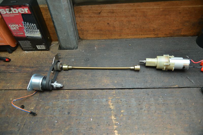
I've got a flexible shaft that would allow misalignment between the motor and the drive cog but it really is too long as the motor will be well back along the table so it would  probably require a separate mount.

Ideally, I would like to make the whole thing as a single L shaped fitting so it mounts to the end of the table in the two threaded holes Seig have allowed for this purpose. The clutch will only stick out about 80 mm which I can live with.

So a question for the experts. Could I cut the flexible shaft in half and silver solder it into a hole drilled in a piece of 12L14 steel? or brass? I've got a MAPP torch here and have done a bit of solver soldering copper pipe etc but was not sure it could be used for something like this. I don't know what material the shaft is made of. It is brass coloured but I doubt it is brass.
RodW
Brisbane, Australia

Offline RodW

  • Full Member
  • ***
  • Posts: 120
  • Country: au
    • Vehicle Modifications Network
Re: Mill Electrotrickery Part 2 - Drilling into Power feeds
« Reply #1 on: May 14, 2013, 01:09:41 AM »
Ooops, I forgot to say that yesterday, I decided to dispense with the trigger and buy a PWM controller out of China on eBay. This is the one I got.

http://www.ebay.com.au/itm/200918663145?ssPageName=STRK:MEWNX:IT&_trksid=p3984.m1497.l2649

There are cheaper ones but I wanted to make sure I could run this off a 18.5 volt power supply from an old laptop  so th eclutch is close to its expected voltage range. The motor is rated to 14.4 volts but I don't think it will hurt to drive it at a slightly higher voltage.
RodW
Brisbane, Australia

Offline andyf

  • In Memoriam
  • Hero Member
  • *****
  • Posts: 1795
  • Country: gb
    • The Warco WM180 Lathe - Modifications
Re: Mill Electrotrickery Part 2 - Drilling into Power feeds
« Reply #2 on: May 14, 2013, 05:25:26 AM »
Rod,
You might be interested in one or two of the ideas shown here
 http://mikesworkshop.weebly.com/mill-power-feed.html , which was a design I co-operated in.

In particular:
1. The way the "stop bar" across the front of the table isn't fixed, but shifts slightly left or right when either of the adjustable stops on it bumps up against the fixed stop. This means that, to save space, both the limit switches can be beyond one end of the table, positioned close together with their operating plungers/levers facing one another, and are operated by a collar fitted to the stop bar so  that, as it shifts, the collar opens one of the switches. The version in the link is even more compact.

2. The use of a relay to switch current to the motor, and to short it out so when a limit switch is tripped, the motor doesn't freewheel and drive the table beyond the stop point. The relay means that the limit switches can be low-current microswitches.

3. The electrical circuitry; it took me a while to work that out. A real rat's nest of wiring, but it incorporates a switch (SW1) to set the direction of cut and another (SW2) to set the table in motion. SW2 starts the table off (moving at a speed set by the PWM controller). At the end of a cutting pass, a limit switch is tripped so the table stops. It will not restart until SW2 is flicked over, whereupon the the motor reverses with the PWM controller bypassed, so the table returns at full speed until it trips the limit switch at the other end and stops. Again, it will not restart until SW2 is flicked back again, whereupon the table starts off slowly under PWM control for the next cut.
SW1 sets the desired directions for cutting and return passes- slow cut to the left, fast return to the right, or vice versa. Setting either switch to its centre off position turns the whole contraption off. The toggle switches are orientated so their levers point in the direction that things are going to happen

Andy

Edited to correct typos.
« Last Edit: May 14, 2013, 09:06:23 AM by andyf »
Sale, Cheshire
I've cut the end off it twice, but it's still too short

Offline RodW

  • Full Member
  • ***
  • Posts: 120
  • Country: au
    • Vehicle Modifications Network
Re: Mill Electrotrickery Part 2 - Drilling into Power feeds
« Reply #3 on: May 14, 2013, 06:59:22 AM »
Andy, Thanks for that. Very nice indeed. It is similar to what I envisaged. I had not given much thought on how to use the limit switches so I need to read your circuit description a few times.
RodW
Brisbane, Australia

Offline andyf

  • In Memoriam
  • Hero Member
  • *****
  • Posts: 1795
  • Country: gb
    • The Warco WM180 Lathe - Modifications
Re: Mill Electrotrickery Part 2 - Drilling into Power feeds
« Reply #4 on: May 14, 2013, 09:42:36 AM »
Hi Rod,

Just ask if you get lost in the maze, but the following may (or may not!) help:

In the diagram, SW1 is wired like a DPDT reversing switch, but instead of reversing positive and negative, it reverses "plain 0V" and "pulse modulated negative" over. That swaps over the directions in which slow cuts and fast returns are to take place.

Two throws of SW2 (its left-hand half) are wired like a straightforward DPDT reversing switch, with its outputs swapping between positive on the one hand and negative (either plain or modulated, as supplied by SW1) on the other hand.

The extreme right-hand throw of SW2 feeds positive to whichever limit switch the table is heading towards, and that positive is sent on to the relay coil to keep the motor switched on until the table opens that limit switch.

The remaining throw of SW2 is not needed if the "Limit switch reached, so I've stopped!" piezo is omitted. In that case, the red positive line below SW2 would be connected to the common terminal of the extreme right-hand throw. If the piezo is incorporated, it won't beep while one of the limit switches is sending current to the relay coil, because both terminals of the piezo are then at the same positive potential. However, when that limit switch opens, the bottom terminal of the piezo goes negative so it beeps. The impedance of the piezo is huge compared to that of the relay coil, so the tiny voltage on the coil isn't enough to operate the relay.

Andy
Sale, Cheshire
I've cut the end off it twice, but it's still too short

Offline RodW

  • Full Member
  • ***
  • Posts: 120
  • Country: au
    • Vehicle Modifications Network
Re: Mill Electrotrickery Part 2 - Drilling into Power feeds
« Reply #5 on: May 25, 2013, 08:25:27 AM »
I am afraid this project has one to the back of the list for a while. I decided that I would use a proper variable speed motor controller that includes forward and reverse.. I was really impressed how quickly I received this out of China.


I am working hard to build a new lathe stand after I tipped my lathe over a week ago so it is taking precedence. Please bear with me as I work through a few projects.

RodW
Brisbane, Australia