Its been a while since I posted but I have been busy designing and starting to make parts.
One of my design criteria is to retain manual operation via the handwheels and the built in dials from the original machine which are 4mm per turn.
The new ballscrew is 5mm pitch and is right handed. The drive is therefore require to correct for these 'challenges'
This is a cross section through the Y axis drive.
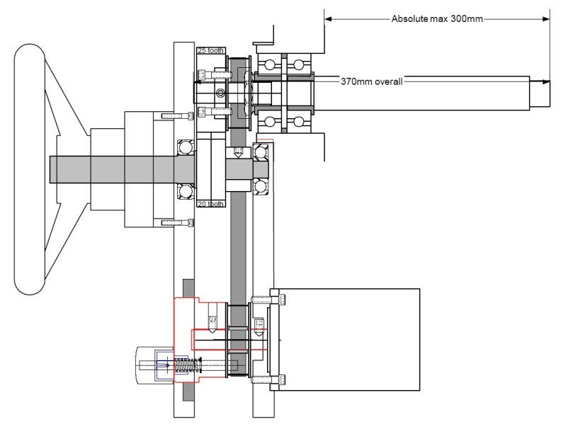
At the top left is the new ball screw supported by a pair of AC bearings. The screw spindle has a 26 tooth HTD pulley secured by grubscrews and to this is bolted a 25 tooth 2 module spur gear. This gear meshes with a home made anti backlash 20 tooth gear which drives the handwheel and original dial.
The gears both correct the pitch ratio and provide a reversal of rotation.
The 26 tooth pulley is connected to a similar pulley (1:1 ratio) via the belt. The lower HTD pulley has been bored to take a needle roller bearing and is free to rotate on the motor shaft.
A simple pin clutch is permanently driven by the motor and when the spring loaded pin is engaged by pulling and rotating the knob by 90 degrees picks up on one of the 4 holes in the pulley.
Now for the pics
The top htd pulley showing the recess for the AC bearing preload adjustment nut
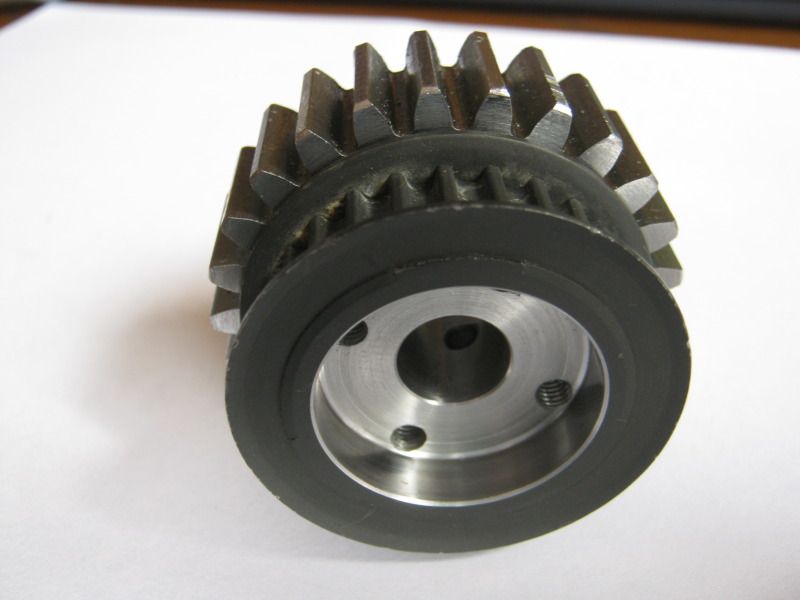
View of the other end showing the 25 tooth gear
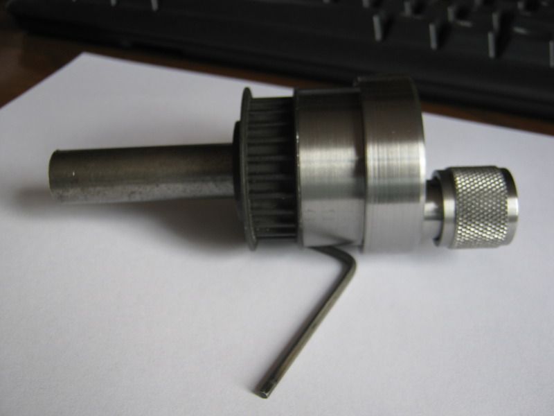
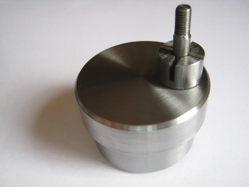
This is the completed clutch mounted on a dummy motor shaft
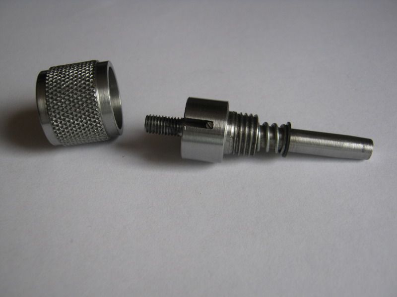
and the component parts.
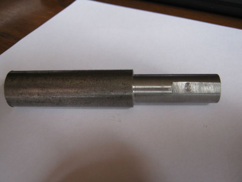
Dummy shaft - not pretty but functional for testing
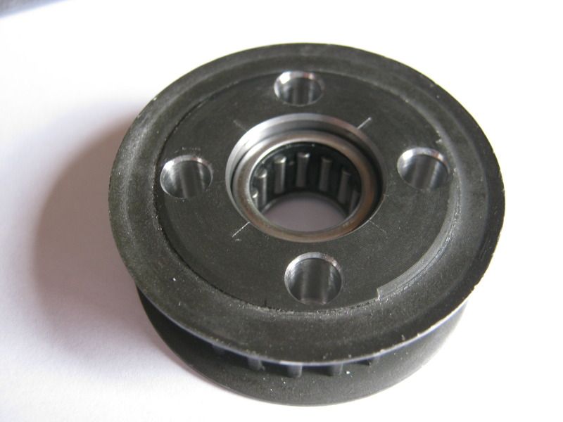
The lower HTD pulley with needle roller and four holes for the clutch pin.
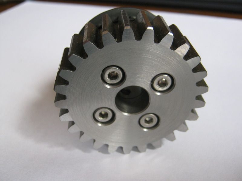
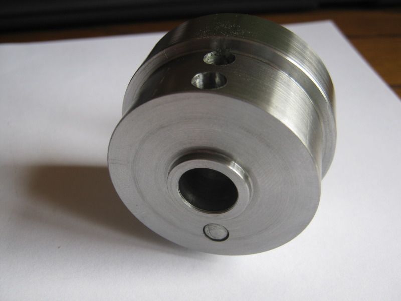
This is the driven part of the clutch with the pin withdrawn
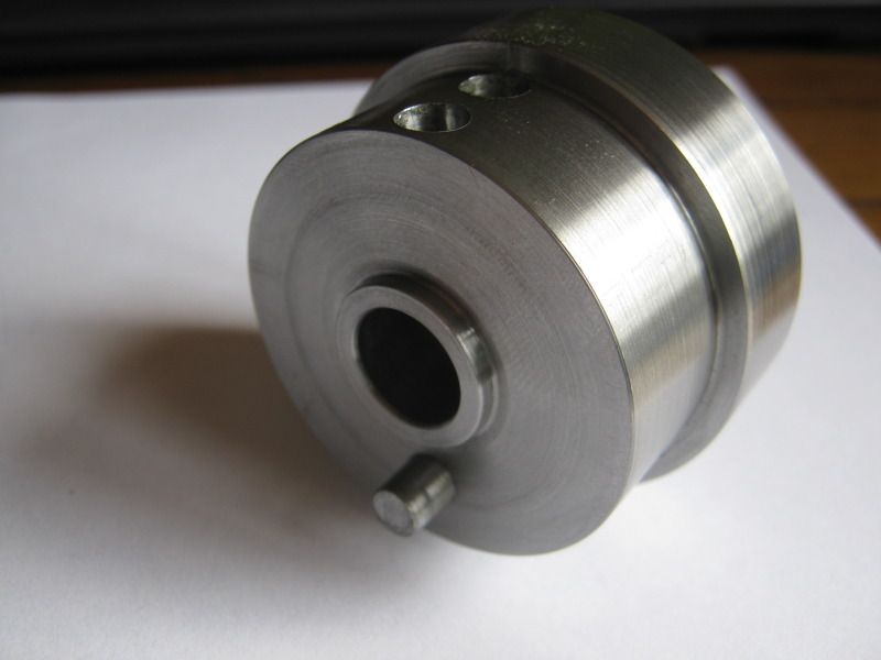
and with the pin in the locked position
The external view of the clutch with the pin withdrawn.
Rotating the pin by 90 degrees allows the clutch to move to the engaged position.
This is the sprung loaded pin and the knurled operating knob which also acts a cover for the mechanism.
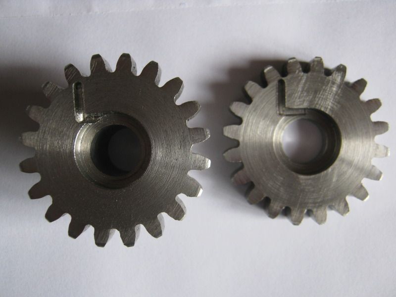
The two spur gears were purchased ready made ( life is too short!) from
http://www.technobotsonline.com/ and arrived next day!
The teeth are 20mm wide and I parted the 20 tooth one into two halves and machined the recesses for the torsion spring.
The spring installed
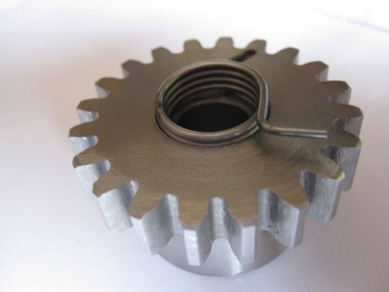
and the two halves re-assembled
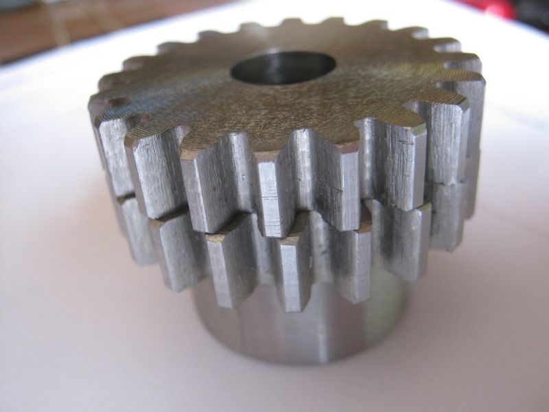
After parting off and cleaning up the tooth width is 17.5 mm so I reduced the tooth width on the 25 tooth gear to match.
I've yet to see how effective the antibacklash device is. The spring allows about half a turn (10 teeth) maximum so reasonable scope for adjustment.
I've shown the details for the Y axis here but there are similar requirements for the X axis. The only difference being the the original X feed screw is the same hand as the ballscrew and so the geared drive is not required. Instead, the 5:4 ratio is provided by a 30 & 24 tooth htd belt on the right hand end of the table and a 1:1 motor drive will be fitted on the left hand end
Thanks for looking.
Bob


