Author Topic: Installing a DRO on an old lathe  (Read 12102 times)

Offline madjackghengis

  • Hero Member
  • *****
  • Posts: 717
  • big engine
Installing a DRO on an old lathe
« on: July 08, 2010, 11:46:41 AM »
About two years ago, I got a DRO for my lathe for Christmas, and have waited to clean and fix up the lathe before installing it, and not willing to take it out of service even for a week or so, have had the DRO on the shelf eating its head out in the stable, so to speak.  In my radial engine build, I found it necessary to remove the headstock of my lathe, and do a general cleanup of the whole of it, and got a chance to measure all the ways and check for wear, and turned out surprised, needing no real work, just lots of elbow grease cleaning up fifteen years of swarf.
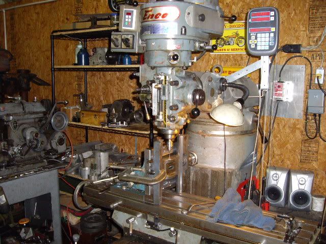
   A couple weeks ago, having had a bad morning, I decided it was time to take a break and do the duty of installing the DRO.  It is a "Shooting Star Technology" setup, using racks with pinion encoders, with an accuracy and readout of half a thousandth, and one I've had working on my mill for some time with good results.

  First off was establishing where the X axis would be placed.  Plenty of room at the back, and no interferance as long as I don't put on my taper attachment, which I haven't used in years.

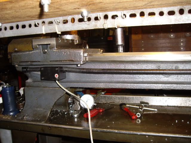
traversing the carriage to the tailstock end, ensuring proper clearance, and establishing where the mount hole for the rack will be

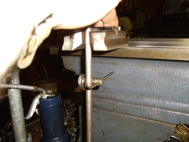
marking out the heighth from the rear way on the tailstock end with a surface gauge

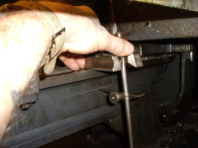
marking out at the headstock end with the gauge still at the same setting

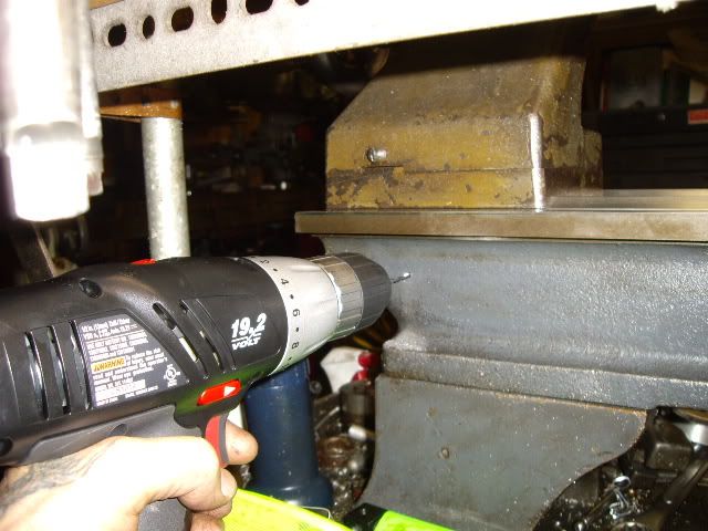
drilling the mount hole at the tailstock end of the bed

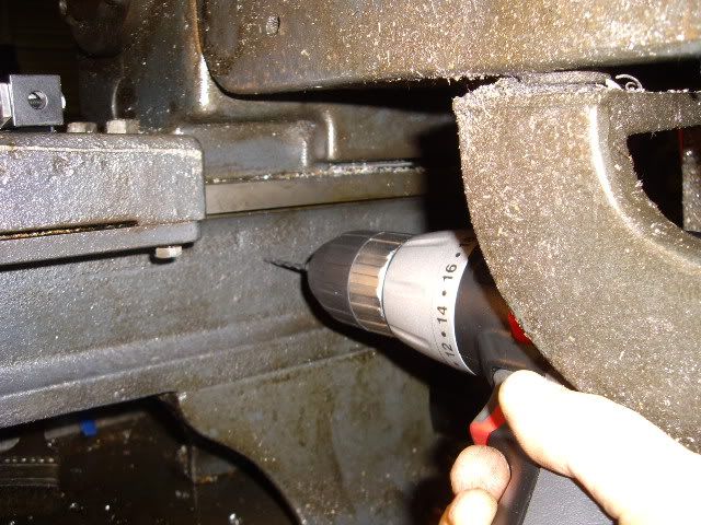
drilling out the headstock end mount hole

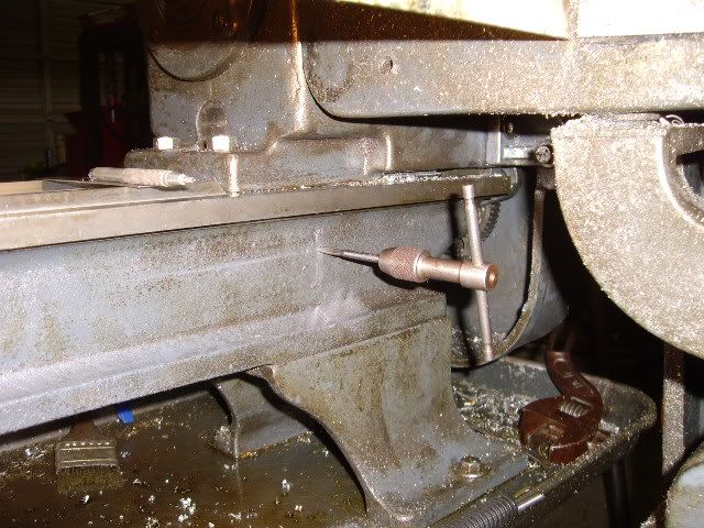
tapping for the 10-32 mount screw

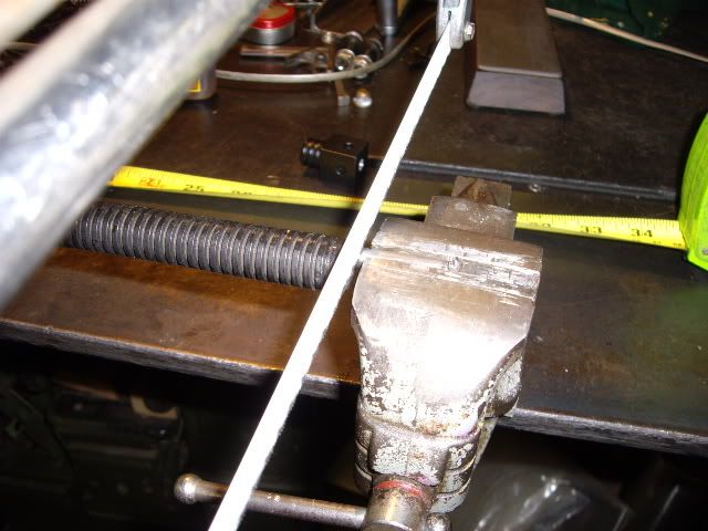
cutting the rack to size

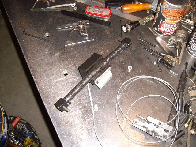
bending up a piece of eighth by half inch stock to mount the readout head for the X axis

two straps cut and fit to hold the readout head secure and accurately

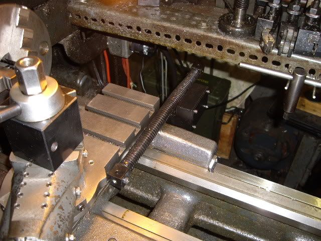
looking at the cross slide, planning for mounting the rack and read head on the front of it

choice made, rack cut to length, bracket to attach the readout head attached to the bottom of it, to screw to the carriage

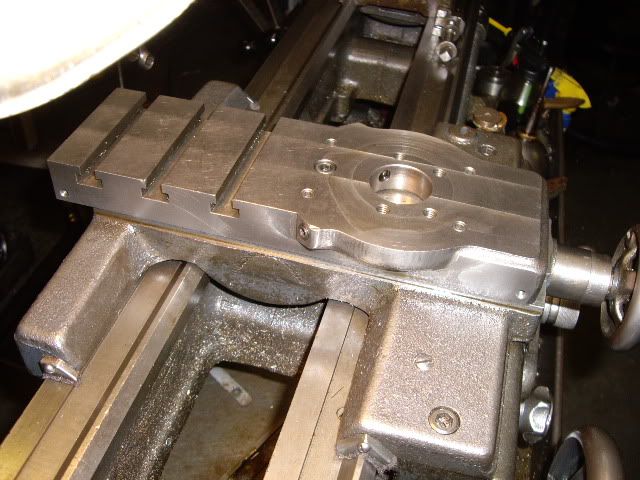
cross slide drilled and tapped, remounted on the carriage, note holes at each end of the slide for mounting the rack

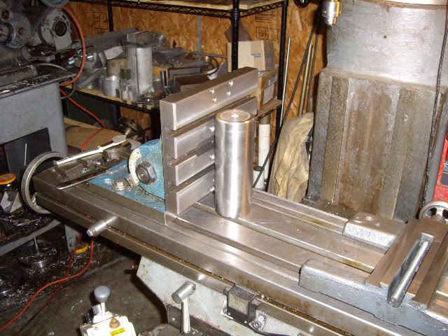
setting up the angle plate to support the carriage vertical, for drilling the readout mount holes

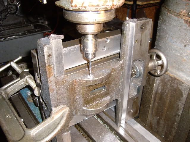
drilling mounting holes in the carriage

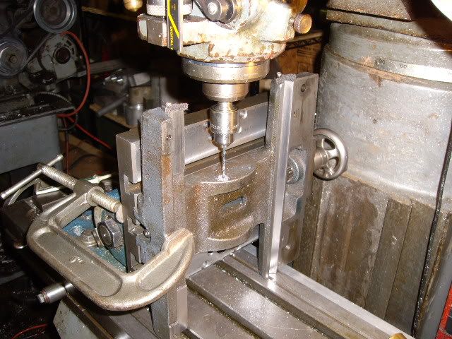
another view of the set up for the carriage

a perspective shot of the carriage on my mill.

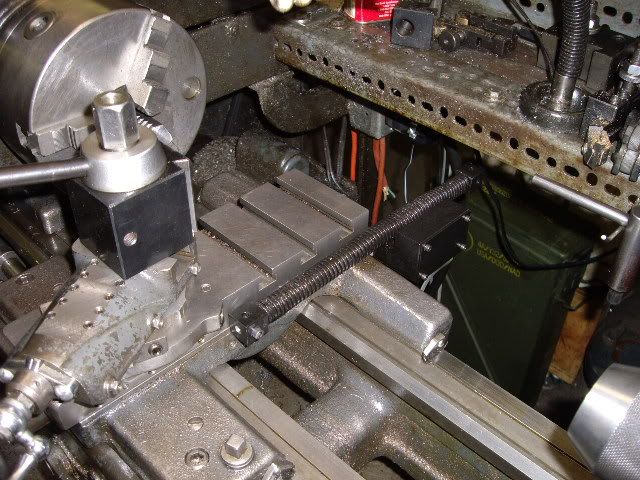
carriage reassembled to the lathe with the cross slide set up for assembly on the carriage for mounting the rack and readout head

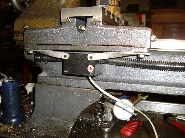
cross slide in place with rack and readout head mounted, not happy, I've lost two inches of room in front of the carriage, and put the readout head in the best place to collect swarf and get hit with a chuck.

another view of a bad choice

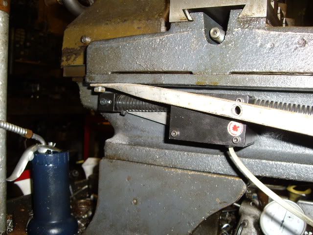
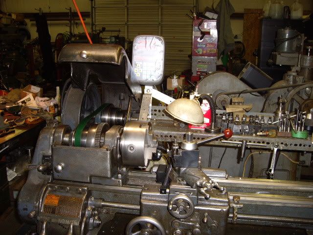
a week later, with the rack and readout head mounted on the rear of the carriage and slide, a much better set up.

Another view of the completed installation, everything working as designed.

Offline Bernd

  • Madmodder Committee
  • Hero Member
  • *****
  • Posts: 3688
  • Country: us
  • 1915 C Cab
    • Kingstone Model Works
Re: Installing a DRO on an old lathe
« Reply #1 on: July 08, 2010, 12:37:22 PM »
OK, Jack, I just gotta' ask.  :D

In the second picture from the top it looks like the rack is bent. Question: is it an optical illusion? Or is it that flexible?

BTW, nice write up on installing the read out. :thumbup:

Bernd
Route of the Black Diamonds

Offline madjackghengis

  • Hero Member
  • *****
  • Posts: 717
  • big engine
Re: Installing a DRO on an old lathe
« Reply #2 on: July 09, 2010, 09:52:05 AM »
Hi Bernd, I'm glad you asked, truth is, the rack is about five sixteenths diameter and the plastic cover is about five eighths, with a bronze tube/bearing at the point where the pinion of the digitizer meets the rack, the plastic cover swells as it goes over the bearing, and that is what you are seeing as curved.  I put the rack/reader in front as the pictures show, and did one job with it like that, boring out a wallowed out dump truck wheel hub for a sleeve to fit a new outer bearing, and watched all the cast steel/iron pile down in the reader, took great care not to hit the reader with the chuck jaws, and decided on the basis of that  job that losing two inches in front of the chuck was far too much to lose, and losing an inch between the tailstock and the rear of the carriage was far more acceptable, thus the moving of the rack and reader, and I'll probably add a triangulated support bar to support the far end of the rack, but right now, it's just floating out in thin air.  It's solid and workable but would be damaged if I ran the carriage back and there was something hanging down in back that was solid and they hit.  On the wheel hub, I had to sleeve it as the bearing surface for the outer bearing was loose, and it was eating bearings.  I took a light cut of about ten or fifteen thousandths, measured the bore and punched in the diameter, took several roughing cuts, ultimately taking out about three eighths for a sleeve to go in, and found the numbers on the DRO matched the measured diameter within half a thousandth, so I think this was a successful upgrade and well worth the effort.  It's nice to read out a cut in an actual diameter change, and know the numbers are right, I've never experienced that before on a lathe.  I expect the X-axis will be an equal boon, particularly in dealing with shoulders on shafts as is common with gear shafts and the like, as well as boring our cavities, such as the one in the crankcase of the radial.  It is within ten or fifteen thousandths of what the plans call for, and that was as good as I could get it using a boring bar, a carriage stop and carriage travel dial indicator with two inches of travel, and working on paper to figure out what was left to cut on which end of the inside of the cavity, and the plans show this is normal, as there is a note to adjust the position of the front bearing shoulder to accomodate the final results and center the crank, suggesting my experience with the cavity is common.  I only wish I had mounted the DRO on the lathe when I got it, two plus years ago, and not waited so long to install it.  I wonder if anyone has ever put a DRO on a shaper?  By the way, thanks for the complement on my write up, I appreciate it, and hope someone with questions gets some use out of it.  I know I have gotten lots from this forum even in just the couple months I've been on it, lots of inspiration, and lots of fresh perspectives and new ways to get around old corners.  Makes me want to quit taking in work and only work on my own hobby things.  It's good talking with you, too, and I feel like these are conversations, mostly.  Truly a pleasure to have the forum.  Ta ta for now, jack

Offline Bernd

  • Madmodder Committee
  • Hero Member
  • *****
  • Posts: 3688
  • Country: us
  • 1915 C Cab
    • Kingstone Model Works
Re: Installing a DRO on an old lathe
« Reply #3 on: July 09, 2010, 02:40:28 PM »
I figured that it might have been a cover since you said "rack". It acutally looks more like an acme screw though.

Thanks for the explination though.

Bernd
Route of the Black Diamonds

Offline Davo J

  • Sr. Member
  • ****
  • Posts: 475
  • Country: au
Re: Installing a DRO on an old lathe
« Reply #4 on: July 09, 2010, 11:20:58 PM »
Great right up,well explaned  :clap:
To answer your question about DRO's on a shaper I saw one on Practical machinist. I picked up a few glass scales that are compatable with my read outs (TTLsignals) that I am putting on my shapers, not sure about the down feed with the cord and vibration, so I may put a caliper on there.
Dave

Offline madjackghengis

  • Hero Member
  • *****
  • Posts: 717
  • big engine
Re: Installing a DRO on an old lathe
« Reply #5 on: July 10, 2010, 11:32:19 AM »
Hi Davo, I take it you are a fan of shapers yourself, given you mention "shapers", and not "shaper".  I'm thinking two axis' on the shaper would be sufficient, the cross travel, for width of cut channels and repeatable dovetail work, and down feed for repeatable cuts in all situations.  My real important issue with my currently operating shaper is the need to put an automatic feed for the down feed, that is reliable at all lengths of stroke, can adjust to angle cuts without losing accuracy, and can have a fixed "last cut", not based on a physical stop, but on stopping the ratchet feed which will be necessarily a part of it, if it is a mechanical down feed arrangement, which seems to be a logical means.  Not too complicated, just too far down on the projects list, and not gotten to yet.  I'm rebuilding an old twelve inch shaper from line shaft days, so all modifications to my small atlas shaper have to be equal to being adapted to the larger one, as it will be the mainstay in that department, when it is completed.  Thanks for the comments, and for the reinforcement of the idea of DRO on shapers.  I use a cut off six inch digital caliper for my down feed on my Bridgeport clone from Enco, didn't cut off the last inch of it until I was sure it would be a permanent installation, but it works great, and was far cheaper than the read outs sold for the purpose.  :headbang: mad jack