Some time ago, I was admiring someone's build of a very nice looking stirling cycle engine, and on inquiry, was given the name of Jerry Howell, and with an exchange of money for prints, I got the plans. It's been so long I've forgotten when I got them, but after fiddling around with some flame suckers, I decided it was time to build something I'd paid good money for the plans, and it was time to build a stirling. This engine is a "beta" type, with the power piston and the displacer working in the one cylinder, and like most of my engines, it will definitely digress from the plans, as I always seem to run across material which will work, but isn't exactly the size or shape the plans call for, yet I'd rather not buy material when I have a suitable substitute in my shop stock.
As usual for me, I started with the cylinder, and of course the deviation started right there. The stock list calls for an inch and a half square piece of stock, and what I had was a piece of inch and 3/4ths round, so I chucked a piece of it in a three jaw, set up the tailstock and drilled a center hole, and started with cutting fins on the blank, and going with a piece of brass tube pressed and locktited in place for the graphite piston to slide on.
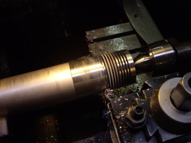
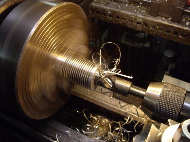
This is the stock as I start making fins, using a .093 cut off blade with the end tapered and radiused. The stock is cleaned up at 1.720 for a nice finish before starting the fins.
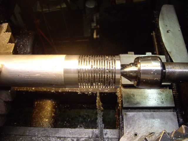
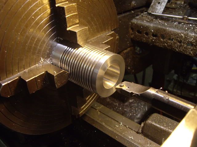
finishing up the fins, about ready for cutting off, I just have to round over the fins with a triangular file and I'm done with this part.
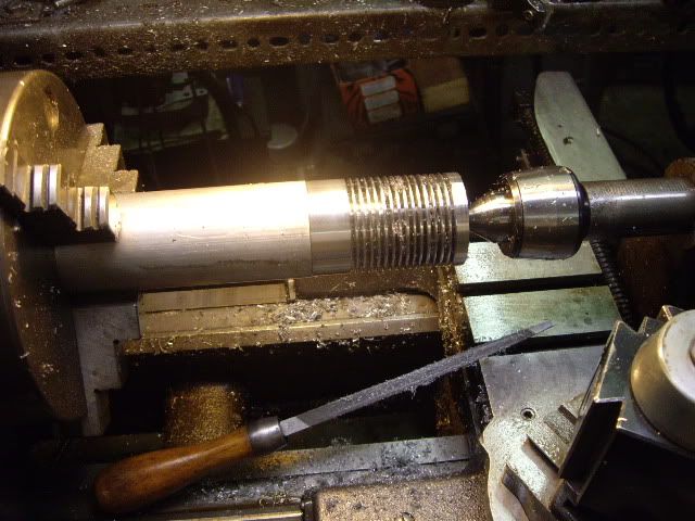
ready to cut off, nice shiny round edged fins, done rather easily with just rolling the file from one fin to the next, hitting first one side and then the next.
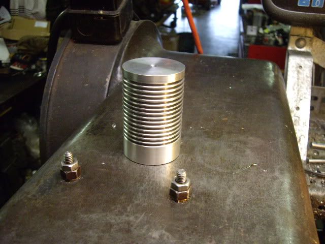
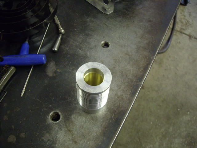
Cylinder cut off, ready for boring for the brass liner.
I tried the cylinder in the three jaw, but didn't like six thousandths runout, so its in a four jaw, and step drilled up to 15/16ths, to be bored for 1 inch brass tube, laying around, not the 3/4 it's supposed to have, but things have a way of working out anyway.
Bored to size, I smeared loctite inside the cylinder and outside the brass liner, and put it in the press. Unfortunately, the sleeve stopped about a quarter of an inch short, but the cylinder is slightly long on purpose, so I cut off the excess brass sleeve, and put the cylinder back in the four jaw, and centered it up to bore the brass liner.
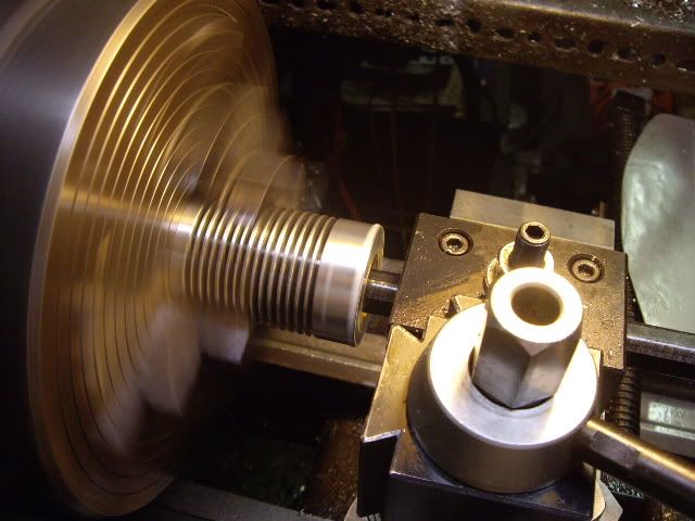
Taking a final pass as my finest power feed, the bore is somewhere about .921 with about half a thousandth of taper which will get lapped out later. For now, I have to make some adjustments in the plans because my cylinder puts the stanchion holes in different locations, and I have to use some angle stock rather than plain 1/4 flat stock.
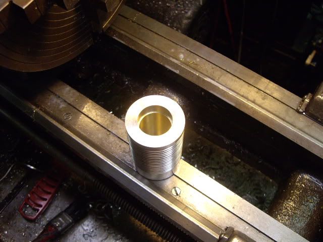
cylinder bored, ready to clean out.
sitting on the bench, you can see the shortfall of my pressing action, and the gap left, this will be filled with the upper part of the stainless heat cap, mostly and with insulation and won't interfere with piston or displacer travel.
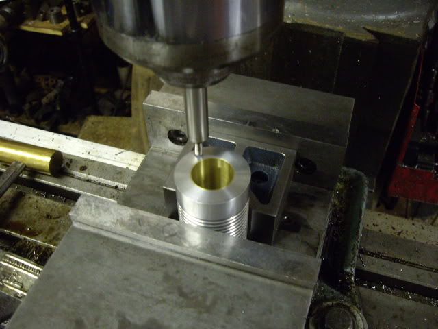
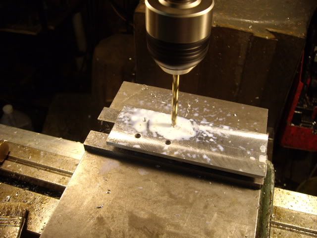
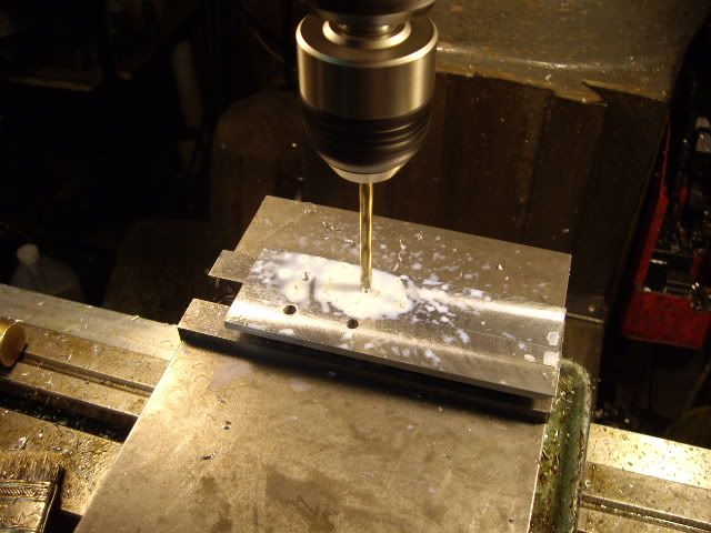
With the cylinder in a V block clamped in my milling vise, I centered the cylinder with a wiggler, and set up for four holes to affix the stanchion to.
Four holes, center drilled, drilled and tapped for 10-24 screws, now some calculations to put the stanchions for the mainshaft and operating levers in proper relationship.
holes done, sitting next to the piece of channel I will cut the stanchion parts from, the angle gives me metal to move the sides out from center, distance lost by using the round stock versus the square. It is split down the middle, and the two halves clamped together in the milling vise, the width of the base milled, taking equal amounts off both sides, then the holes will be drilled for the screws to hold them to the cylinder.
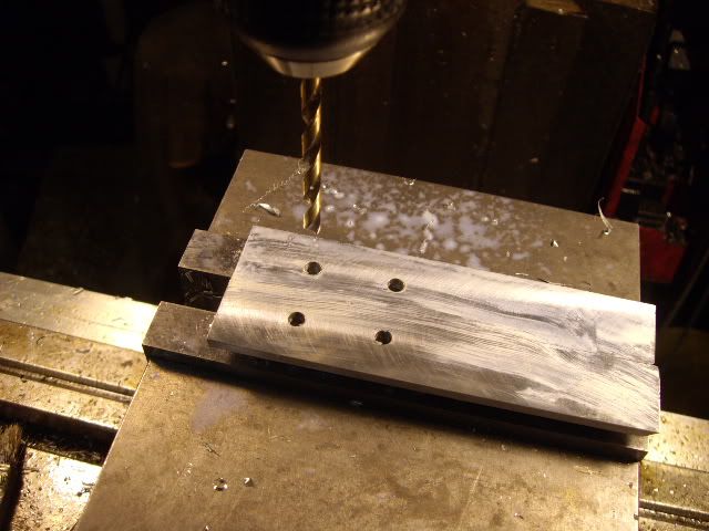
holes located from the edge with a wiggler, then center drilled, and drilled clearance size for the #10 screws
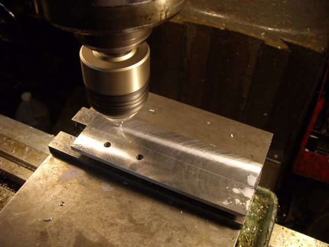
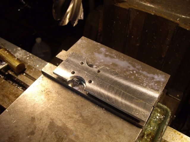
holes completed, now it's time to clear space for the rod and actuating arms to work through.
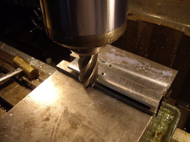
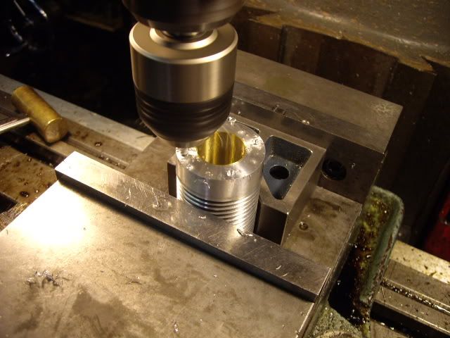
I used a 1 in end mill, and centering it between the holes, used it as a bore, taking a .100 bite at a time until I'd gone in .500 from the edge, and then touched off the opposite side, and did the same thing, with the stock being clamped by the uprights which will serve as the stanchions.
here you can see the cut-outs which will encircle the cylinder when bolted in place.
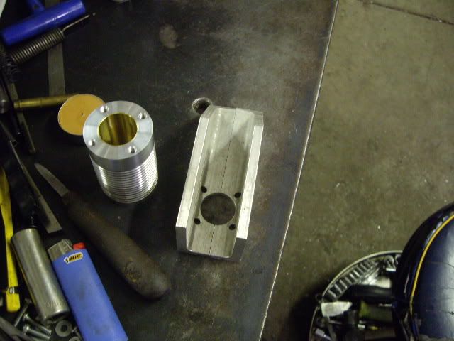
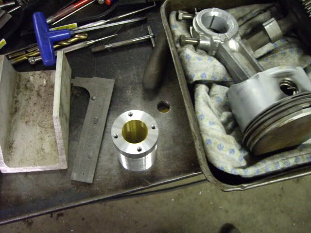
here is the cylinder, next to the two pieces of angle which are in the position they will finally be in, after all the excess is removed, and they look like stanchions. The box next to them is the engine of my lawn tractor which got filled with water with our last flood, and is being rebuilt after drying out. I hope this build log is as enjoyable to others as so many have been to me. Cheers, mad jack


