Author Topic: building a new flame sucker  (Read 45247 times)

Offline Stilldrillin

  • Global Moderator
  • Hero Member
  • *****
  • Posts: 4972
  • Country: gb
  • Staveley, Derbyshire. England.
Re: building a new flame sucker
« Reply #50 on: January 08, 2011, 02:22:29 AM »

Were dose the hand grenade go  :scratch: 

Anywhere it wants to, if ever it goes bang!  :lol:

David D
David.

Still drilling holes... Sometimes, in the right place!

Still modifying bits of metal... Occasionally, making an improvement!

Offline Bogstandard

  • Bogs Group
  • Hero Member
  • *****
  • Posts: 1107
Re: building a new flame sucker
« Reply #51 on: January 08, 2011, 03:13:29 AM »
I have not commented yet Jack but I am following this build avidly. I love 'home mades' and how people get around the small problems.

Now for the comment.

Flame gulpers normally have very little power output, mostly 'gnat' power. So if you do start to have problems getting it to run, go on a lightening exercise on all the moving parts first, skin them down to the bare minimum.


John
If you don't try it, you will never know if you can do it.

Location - Crewe, Cheshire

Skype - bandit175

Offline NickG

  • Madmodder Committee
  • Hero Member
  • *****
  • Posts: 1890
Re: building a new flame sucker
« Reply #52 on: January 08, 2011, 07:07:18 AM »
Olli, I was wondering that but found one of his previous posts with a sort of mock up position - think it's going to be angled but opposite to the duclose one if that makes sense?

Nick
Location: County Durham (North East England)

Offline madjackghengis

  • Hero Member
  • *****
  • Posts: 717
  • big engine
Re: building a new flame sucker
« Reply #53 on: January 08, 2011, 11:44:59 AM »
Hi all, thanks for all the interest and interesting comments, much appreciated.  This engine has sort of decided its self how it would work, and what it will look like, but I've managed to get it to a point where I really like it, and it's close to eating some flame.  I had to take my dog to the vet yesterday, he started limping the night before, and as it turned out it had nothing to do with the fibrous growth on his foot, but a torn ligament in his knee, so Buddy's on bed rest for about eight weeks.  When I got home, I put him to bed, and went right to the shop and got started where I left off.  It was hard to leave off the night before, so close, however it was good to know exactly where to start.


having played with the valve lever I knew where I wanted the pin to be, so I set the lever up in the mill vise, centered a #1 center drill by eye, drilled, and then drilled the hole 1/16th, about half an inch deep at what I think is a good angle.


when it is running, I expect to mill out some of the lever and "skeletonize" it, for lighter weight and looks


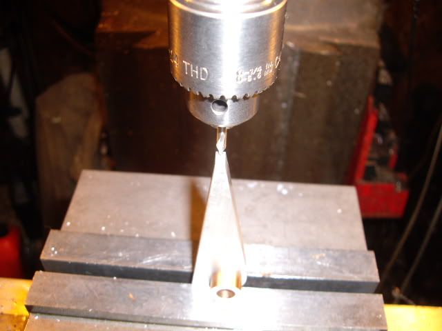
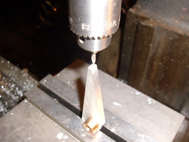
with the lever in place, I was able to establish the place for the hole for the pin in the valve carrier extention, and drill with some wiggling of the extention in the direction the pin will angle during valve actuation, the pin is in place, with a piece of spring cut from a bic lighter flint spring, cut to length


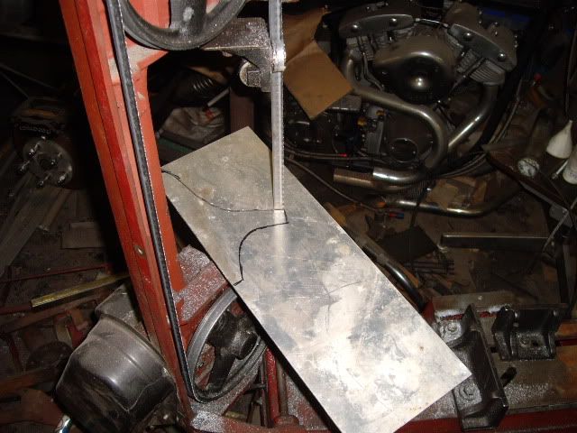
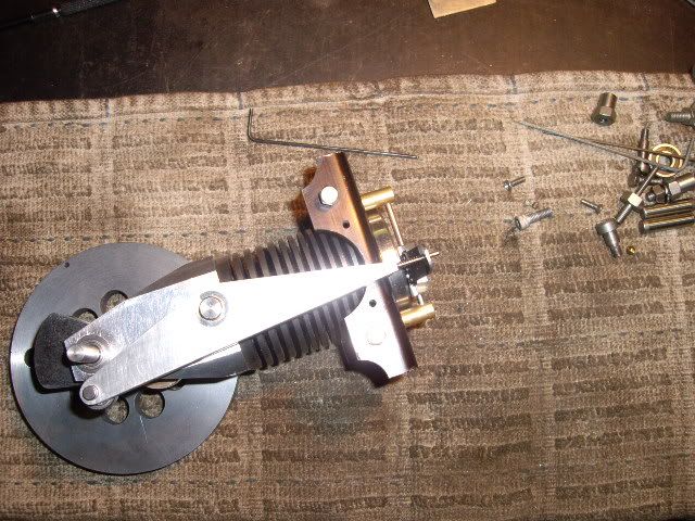
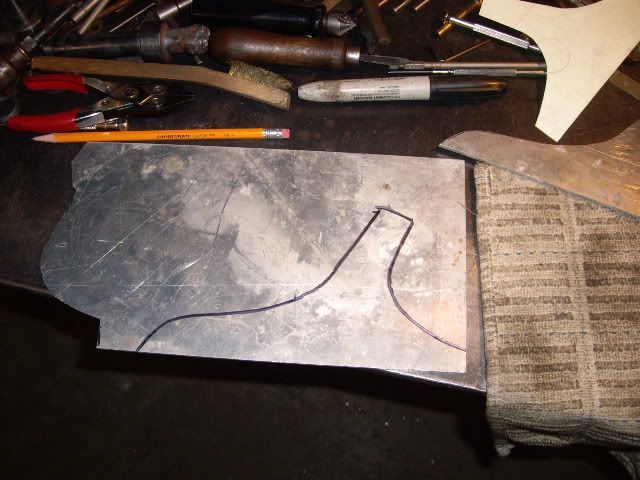
after playing with the valve for a while, I laid the "engine" on my pad of paper, sketched around it with a pencil, then without the engine, cleaned up the lines and curves, cut out the paper pattern, and copied it onto the 1/8th in aluminum with a marker, then put the plate on the bandsaw to cut out the first side


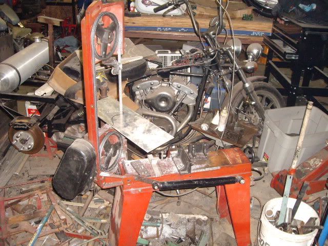
The bandsaw, standing in the middle of much of the scrap it produces, going on twenty five years, rebuilt the first week I had it, and running with only a few repairs along the way, and Chinese :lol:


the second side, traced from the first


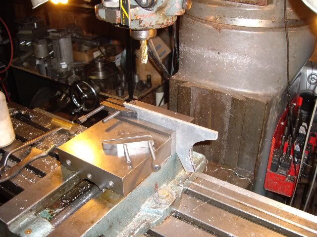
after cutting the second side, setting up in the mill to get the bases even and straight


clamps in place to minimize vibration, taking about a 15 thousandths cut off the bottom of both sides together


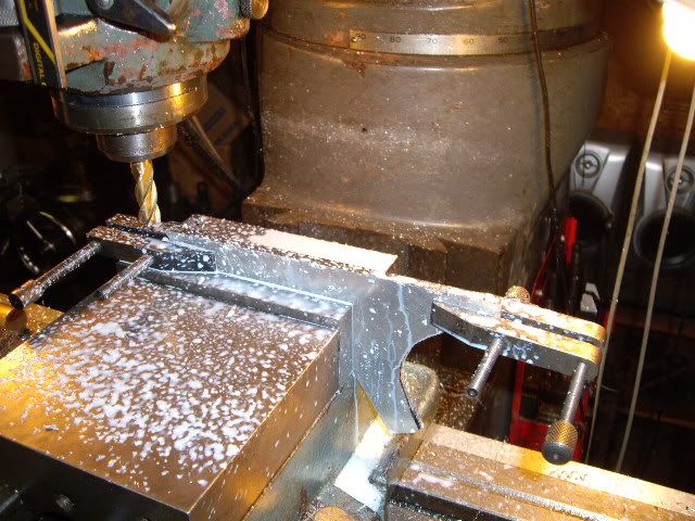
the end of the cut, fifteen was enough, no rough edge left on either side


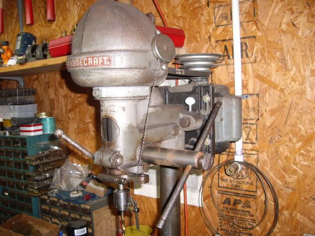
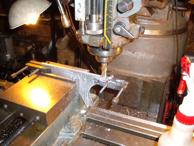
having taken the clamped together plates and cleaned up the profile with a six by 48 in belt sander, I scribed a line on one side and marked out the mount holes for the cylinder assembly, then drilled two holes through both on my small drill press, reserved for high speed, note the chuck key return arrangement, it was on the press when I bought it at a yard sale, a great idea for keeping the chuck key


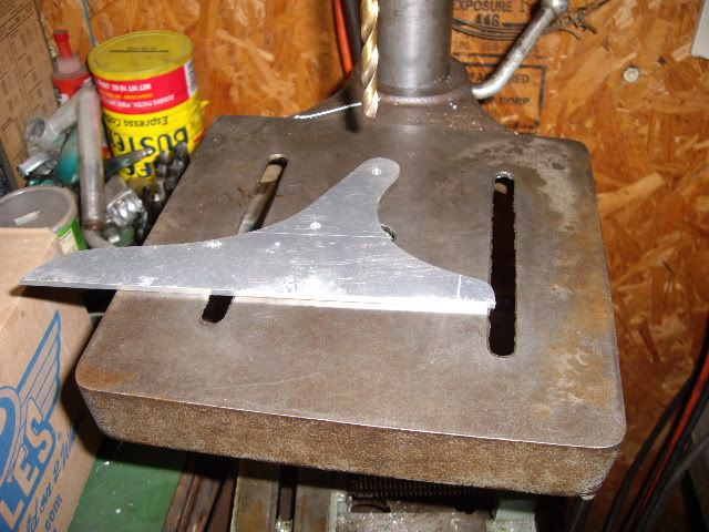
having drilled the first two holes, which are the same on both sides, now drilling two more holes which are only on one side, just the breaks of using recycled pieces for a mounting


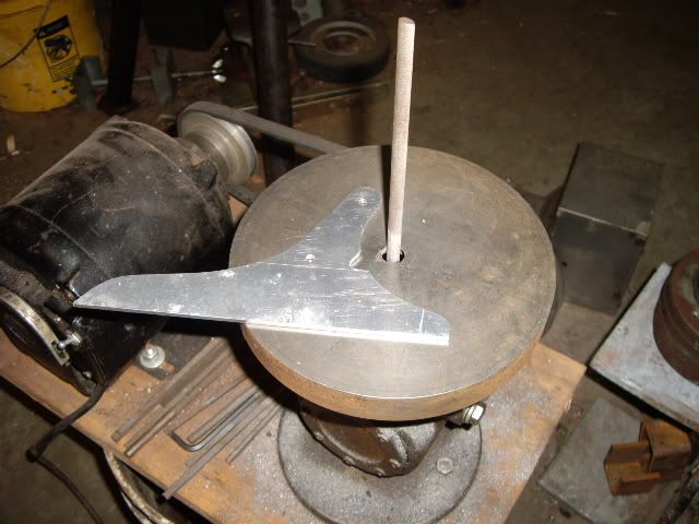
the second side plate interfered with the valve lever a bit, so it got a hole drilled, two cuts on the bandsaw leaving a triangle cut with a radius top, and with a round file in the filing machine, cleaning up the burrs and ugly of the saw cuts, and radiusing the cuts to match the overall flow.  The filing machine is from Metal Lathe Accessories, and is a very nice well designed machine, invaluable for profiling the thin metal especially


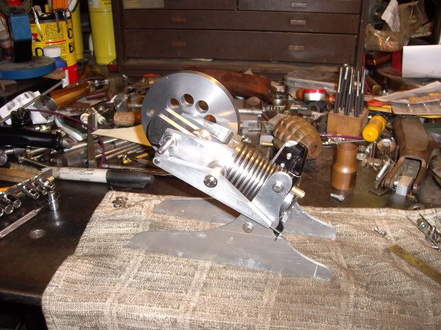
Both sides bolted on, now I get to see live, what I've been trying to see in my head for a while.


another side view with the valve gear easily seen


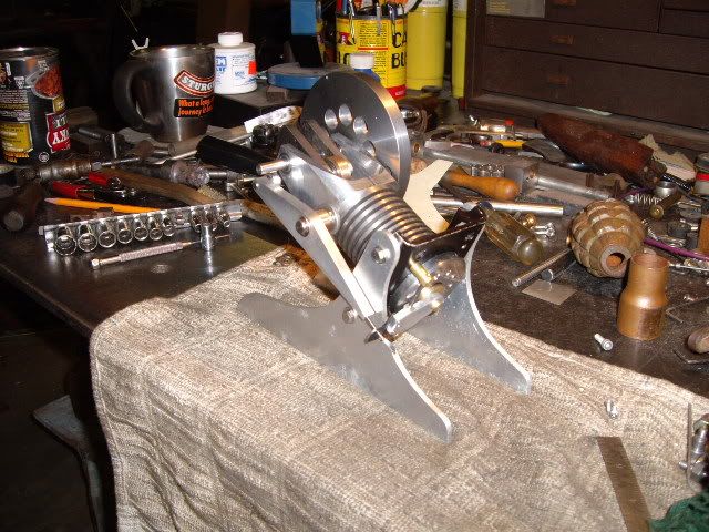
the other side, mostly a view of the flywheel, but looking pretty much like I want


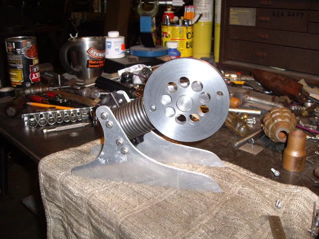
here's a shot of the head end, where the flame will be


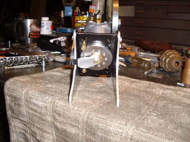
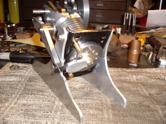
looking straight in at the head, now I have to concoct a cam, having played with the valve lever and measured between the cam roller and a 5/8ths in bearing I slid on the shaft to act as the minimum diameter and baseline for the cam


one last shot, the port is 5/8ths diameter, the bore is 3/4 in, with an inch and a half stroke, the valve is 7/8ths in diameter moving up to open.  I've got to try to do some adjusting on a friend's Volkswagon fuel injection, by ear since I don't have diagnostic equipment, so hopefully it will go smooth, and I can get a cam turned, and maybe be able to put flame to this eater.  Thanks for watching, for the advice, and for all the interesting comments.  I really enjoy the presence of friends and aquaintences participating in such a build, and enjoy being among the audience as well.  Almost feels like a club, I wish I could invite you all to visit, and could return the invite myself.  :headbang: :thumbup:mad jack


Offline NickG

  • Madmodder Committee
  • Hero Member
  • *****
  • Posts: 1890
Re: building a new flame sucker
« Reply #54 on: January 08, 2011, 01:18:23 PM »
Looks good Madjack, a good design as the flame will naturally be going up into the cylinder and the valve mechanism looks like it will give low friction so long as it keeps sliding nicely on those sintered bushes. The one slight concern I would have is the size of the port relative to the bore, will it create a high enough velocity when it's sucking in the flame - may well do in this configuration as it's got the right angle, also, will you get a flame big enough so as not to suck cool air in.

I'll be willing it on, really hope it runs - good luck. If I was a betting man, I'd put a few quid on this one running straight away having learnt from your previous flame eater.  :thumbup:

Nick
Location: County Durham (North East England)

Offline madjackghengis

  • Hero Member
  • *****
  • Posts: 717
  • big engine
Re: building a new flame sucker
« Reply #55 on: January 09, 2011, 11:33:39 AM »
Hi all, didn't get much done yesterday, too much fiddling with fuel injection in a VW, and messing with dragging brake pads on another friend's front end.  I did get a cam blank machined though, and today I should be able to get some actual angles on it, and see about opening and closing that valve on time, and then fixing the engine to a nice piece of old oak or walnut.  I wouldn't mind actually getting it to run today, but that's a "what if", and not a goal, just chance.  I've got an idea regarding flames, resonant chambers and the possibility of making such things work to improve the amount of heat actually taken in by such engines, so I deliberately made the port huge.  We shall see how it all shakes out.  More pictures will be posted, didn't take enough yesterday to remember to bring home the camera.  When you run across a piece of aluminum bronze, cherish it like gold, nothing machines quite like it, and no other bronze is quite as strong and hard, so it is very nice to have, that's what the chunk of unknown bronze I made the cam blank turned out to be, much better than the brass I thought I was falling back on, if you know what I mean.  Ta ta for now,  :poke: mad jack

Offline madjackghengis

  • Hero Member
  • *****
  • Posts: 717
  • big engine
Re: building a new flame sucker
« Reply #56 on: January 10, 2011, 12:13:47 PM »
Hi all, yesterday was interesting, I got the cam machined, I think it's pretty close to right, but not certain yet, and spent the evening playing with the engine while trying to get the cam to just the right place to do what it needs to do.


turning the hub o.d. to the minimal size of the cam actuating lobe


I turned to calculated o.d. for the lobe, and now I'm cutting off the cam trying to save the bit of shaft that is left


I put the cam blank in the milling vise, milled off a straight edge down to the hub


using the swag method, I rotated the cam blank to what looks to be a good angle, and milled again, down to the hub, leaving a couple thousandths for final filing fit

with swarf out of the way, using a wiggler to center the hub for a set screw, or grub screw if you prefer

hub centered


hub centered, center drilled and tap drilled, tapping it for #4-40 set screw


one set screw is an invitation for vibration loosening, so the cam is turned to put another set screw in, now needing centering again, with the wiggler


Centered, drilling with a center drill


drilling tapping size, after center drilling, for the second set screw, then tapping as per the first one


After tapping the second set screw hole, I milled off the sharp point where the two milled flats forming the angle of the cam meet up, to minimize filing


moving the cam by eye, then milling off the sharp corner which will be filed to a radius for the actuating arm to follow


milling off the other corner


the corner, after milling it down thirty five thousandths


while on the mill, centering up the flywheel for its second set screw


the other edge of the flywheel touched off with the wiggler


hub centered, note the extra long center drill to reach the hub past the flywheel


center drilled and drilled, the tap barely clears the top of the wheel, extreme care keeping the tap in proper alignment


when the tap wrench no longer reaches, my four inch crescent wrench comes in handy to complete the tapping operation, never leave home without it, but don't take it to airports


back to the cam, with the rough cam in the vise on the bench, the center is carefully filed down with my finest files, to the hub, matching the radius, and putting a radius of "good proportion" on the corner


another view of the cam in the bench vise


the cam, ready for initial installation


and the cam, finally installed on the mainshaft, now comes the hard part, timing with no specs.  I've spent the rest of the evening moving it around, while comparing valve and piston movement with that of my Duclos flame sucker, having milled the cam a bit more before closing down the shop, because the valve was open too long, I seem to have the timing pretty close, and having gone through my box of miscellaneous springs, I think I will have to wind one, as so far, none seems to fit either being too strong, or too weak.  I think I will try a coiled tangential spring, around the pivot of the lever, with an arm against the lever, and the other arm against some adjusting arm of some sort, so I can vary the pressure on the valve.  I've got some music wire which I think will be about right in size to give good tension, and Herr Bettinger uses such to act as a throttle on some of his flamenfergessen's (flame eaters).  I hope today to have a solid base, a burner with enough flame, and maybe a running engine, touch wood as Nick would say.  I think I have a piece of oak begging to be a part of this piece of work and I like oak.  Ta ta for now, mad jack

Offline NickG

  • Madmodder Committee
  • Hero Member
  • *****
  • Posts: 1890
Re: building a new flame sucker
« Reply #57 on: January 10, 2011, 07:02:07 PM »
Great work on the cam Jack, I think the poppin one is a similar shape. Can't wait - I'll be listening out for it in my sleep then checking again tomorrow at work!

Nick
Location: County Durham (North East England)

Offline sbwhart

  • Global Moderator
  • Hero Member
  • *****
  • Posts: 3530
  • Country: gb
  • Smile, Be Happy, Have Fun and Rock Until you Drop
Re: building a new flame sucker
« Reply #58 on: January 11, 2011, 03:14:32 AM »
Great work Jack looking real well.

Are you going to convert that grenade into the burner   :headbang:   :nrocks:

Stew
A little bit of clearance never got in the road
 :wave:

Location:- Crewe Cheshire

Offline arnoldb

  • Hero Member
  • *****
  • Posts: 515
  • Country: na
  • Windhoek, Namibia
Re: building a new flame sucker
« Reply #59 on: January 11, 2011, 11:10:38 AM »
Looking good Jack  :thumbup: - you're near to firing it up now  :D

 :beer:, Arnold

Offline madjackghengis

  • Hero Member
  • *****
  • Posts: 717
  • big engine
Re: building a new flame sucker
« Reply #60 on: January 11, 2011, 12:07:34 PM »
Hi guys, and thanks, as to using the pineapple for a flame source, I think I'll reserve that option for the slim possibility I don't get it to run, and then it will be one big flame.  On the other hand, it might need a big flame :lol:
    Yesterday, I had to go into the woods to get some firewood and I hit the wetlands part, being dry this time of year, and planned on just picking up a hundred pounds or so of down dead wood.  I call  this part of the property, "Medusa's Vineyard", mainly because it has about a couple dozen trees and a hundred miles of vines in about two acres.  Those lopping shears are four inch, and they only cut the small  vines, I had to use the chain saw for the vines more than my wrist size.


I got my wood, spent a couple hours killing vines, and looking at the ones which swoop up a hundred feet and are too big to cut without the chainsaw.  Ice storm coming so wood is good.


having removed the valve actuating arm to mill out the excess, and to figure out spring mounting, making some chips as I lighten it up


I mounted a four by four by eight toolmaker's block in my vise to give a solid base to clamp the arm to, and still move it easily.


I'm using a .250 carbide end mill at about 2200, and profiling the holes by eye, the cutter makes quick work of the .250 thick aluminum


plunging in for the other angle of the hole


finishing up the holes


cleaning up the final shape on the filing machine, it is great for "pierced work", and the kit was easy to build, nice and solid castings, top quality metal fine tool well worth the work to build.


showing the rough leavings of the mill, didn't want to stray too far, that cutter leaves no room for error


with the holes to shape and done, thinning out the valve end where the spring wire operates the valve carrier


with a half in carbide ball mill, making the radius to end the thin portion


changed over to a fly cutter to take out the bulk and leave a nice finish


down to the last cut, finish thickness, change back to the ball mill to match both depth and clean up the transition


last cuts with the ball mill


after cleanup and deburring, back in the mill vise for drilling for the spring, center drilling with a #1


drilling out to .062, down until I see bronze, and then stop


the lever, finished, deburred, and ready to go back on


another view


the lever back on it's spindle


valve carrier back on, engine back together

I used my small burner for my Duclos flame sucker but it is way too small and didn't even get a pop out of it, but the engine needs to be mounted, and a proper sized flame provided, so that will have to be next.  I still have only timed it by eye, and suspect I probably need to play with that as well, but everything seems to move right, and smoothly, I get to go to the doctor's today, my neurologist wants me to have a "regular doctor", and doesn't like my answer when I tell him I don't have anything wrong with me except the bloody M.S., he says everyone needs a "general doctor".  Maybe this doctor will be willing to take the piece of swarf out of my foot my wife won't cut deep enough to get, and I can't reach myself.  Thanks for watching, commenting, and the advice, it is all appreciated :headbang: mad jack

Offline madjackghengis

  • Hero Member
  • *****
  • Posts: 717
  • big engine
Re: building a new flame sucker
« Reply #61 on: January 16, 2011, 11:16:09 AM »
Well, having played with my flame sucker, without even a hint of action, I've concluded the port is way too big, and there is too much friction in the valve action, moving the valve over such a large port.  I didn't like my alternate choices of material, so I decided to bore out the head, machine an oversized plug to press in, and then put a proper sized port in, with a new cam and valve.


the head was bored, a plug cut .001 oversized and pressed in place with loctite stud and bearing mount


facing off the stub of the plug


facing off the last couple thousandths


head faced off, drilled, reamed out for .375


taper turned in port to improve heat retention of the head


on to the burner, centering the spindle over the pipe fitting for drilling the wick tube


center drilling


hole drilled, ready for soldering


a piece of solder was cut to fit inside the fitting, it set on a cleaned piece of sheet brass, and heated till the solder flowed all around and wicked out


the wick tube soldered in place


turning a cover from some brass rod, one inch in dia.


turning a shoulder for knurling


knurling the shoulder


radiusing the top, using a rod with points on both ends, each fitting in a punch mark, one on the head stock, the other on the cross slide, holding the carriage toward the head stock and letting the movement of the cross slide follow the radius rod, and moving the carriage away from the headstock as the tool comes to center.


a view from the top, note the radius rod down below the chuck


the radius rod, I've made different ones for different radii, the key is cutting slowly, and keeping pressure on the carriage against the rod


the burner complete, now I need to turn a slightly different cam, and turn down the o.d. of the valve, to fit the smaller port and reduce the total movement of the valve train, allowing for a lighter spring tension hopefully getting this engine running.  With a bit of luck the engine should run today, but we shall see.  Thanks for watching, mad jack


Offline Stilldrillin

  • Global Moderator
  • Hero Member
  • *****
  • Posts: 4972
  • Country: gb
  • Staveley, Derbyshire. England.
Re: building a new flame sucker
« Reply #62 on: January 16, 2011, 12:23:11 PM »
Better luck, this time Jack!  :thumbup:

David D
David.

Still drilling holes... Sometimes, in the right place!

Still modifying bits of metal... Occasionally, making an improvement!

Offline Gerhard Olivier

  • Sr. Member
  • ****
  • Posts: 314
Re: building a new flame sucker
« Reply #63 on: January 16, 2011, 06:00:47 PM »
Good luck -you will get it

If you have a moment could we see some pics of your die filer that would make a great preoject


Gerhard
Guernsey
Channel Islands

Offline sbwhart

  • Global Moderator
  • Hero Member
  • *****
  • Posts: 3530
  • Country: gb
  • Smile, Be Happy, Have Fun and Rock Until you Drop
Re: building a new flame sucker
« Reply #64 on: January 17, 2011, 02:17:09 AM »
lever looks good Jack in fact it all looks good.   :thumbup: :thumbup: :thumbup: :thumbup: :thumbup:

I'm sure you'll soon hace it running

Stew
A little bit of clearance never got in the road
 :wave:

Location:- Crewe Cheshire

Offline NickG

  • Madmodder Committee
  • Hero Member
  • *****
  • Posts: 1890
Re: building a new flame sucker
« Reply #65 on: January 17, 2011, 08:17:02 AM »
Jack,

Pity it didn't run first time but I don't think these things ever do!! I'm sure it'll have a better chance with the modifications you have done though. I'm having reservations about mine being able to run now, even though it is supposedly easier to get poppin to run! They really are finicky little things, or in your case finicky big thing!

Good luck, think you're there though. Lightened lever looks great by the way.

Nick
Location: County Durham (North East England)

Offline madjackghengis

  • Hero Member
  • *****
  • Posts: 717
  • big engine
Re: building a new flame sucker
« Reply #66 on: January 17, 2011, 08:32:50 AM »
Hi all, appreciate the comments Stew, Gerhard, David, and Nick, I'm glad someone wants some pics of the die filer, I bought the kit, took a rather short time to build it, and have used in quite a bit since, and it is a very nice addition to the shop.  I will go through the drawings and post what I can, and take some pictures, and post a log on it in the machine section, and link to you, Gerhard.
    I had a short day yesterday, my 27th anniversary, spent most of the afternoon getting a 51 Harley pan head ready for its first start after a bike build, just about an hour's of niggling details and it's ready to fire up, but we spent about four hours on other "niggling details" yesterday, last wiring, fuel lines, oil lines, double checking everything, timing and the like, a good friend's bike, been down for four or five years, and has very few parts that ever ran together before.  A 1937 frame, fifty one bottom end of the engine, 75 top end, that is heads cylinders and pistons, new carburetor 1930 something springer front end, and 1940 wheels and brakes (ugh), been in my shop for about three years kind of like a hobby shop garage for down and out mechanics.  It would be running except the two years of ecconomic relief didn't include mechanics and motorcycle repair business, just wall street.
    I got things sorted out pretty much on the flame eater, with the cam about in the right place, and with the right diameters and it should be close on the overall timing, but I think I need a bit larger valve cover, I think I turned the one I had, down about a sixteenth too small, making for a bad seal on the vacuum side.  If this doesn't get things running, I think I will re-arrange the valve levers and see about inserting a "poppin" style valve train, and valve, as that seems to be about as light and minimal valve train possible for such and engine and I think I'm getting the oil on my sliding valve carrier sticky from getting too hot.  It stays in the flame, open and closed, and probably shouldn't.  I really like the way the "poppin" valve gets totally out of the flame when it's open, and only exposed to it during the short cycle while closed, and able to dissapate heat into the head.  Thanks again for looking and for comments, and I think you will enjoy the die filing machine write up, I know I would be kicking myself if I hadn't built it, I tried many cheap and easy ways around it, but none were sturdy enough and solid, to give a squared off finish, and to keep going without dying on the filings. On top of all that, I've got a great wife, she's happy we didn't go anywhere so she didn't have to get dressed up, and she enjoyed the Chinese I went and got, from our favorite Chinese takeout, about an hour away, some things are a bit away when you live out where the deer and the bears play.  It's good to have a wife that puts up with all our kind of mess, and doesn't want to get all dolled up on an anniversary and was ready to come out and cheer if she heard the sound of that Harley fire up.  :beer: cheers mad jack

Offline Brass_Machine

  • Administrator
  • Hero Member
  • *****
  • Posts: 5504
  • Country: us
Re: building a new flame sucker
« Reply #67 on: January 17, 2011, 01:43:56 PM »
Hiya Mad Jack  :wave:

Dunno how I missed this thread. Nice work! The pictures are excellent. Now that I have read this thread from beginning to end in one shot, I am anxious to see it run.

BTW... Happy Anniversary!

Eric
Science is fun.

We're all mad here. I'm mad. You're mad.

Offline madjackghengis

  • Hero Member
  • *****
  • Posts: 717
  • big engine
Re: building a new flame sucker
« Reply #68 on: January 22, 2011, 11:38:20 AM »
Thanks for all the kind remarks, this has been a challenge, trying to apply several different ideas into one engine has meant lots of learning.  The sliding valve worked great, but the heat burned the oil and caused the slider to stick, so I chose to go with a piece of spring steel pivoting on a spring loaded screw, a leaf from a feeler gauge found on the bench, about .013 thick, punched a hole for the pivot, used a hacksaw blade with the gauge in a vise to cut a slot for the pin to ride in, and drilled and tapped a #4-40 hole in the head for it to pivot on.


it's the same pin which moved the slider up and down, but I had to change out the roller on the arm, as the pin was in the wrong position for the valve to close, so I found another ball bearing, .750 o.d. .250 i.d., replacing a .625 o.d. .1875 i.d., and had to turn a pin with a shoulder to hold the new bearing.


old and new bearing with pins in place


another view of them


here's another view of the engine with its new valve, still not running, but I need to alter the cam, I think it's open too long, not getting enough of a power stroke.  I will be doing some work on it today, and hopefully getting somewhere.  If this valve arangement doesn't do the trick, I think I will coble together a version of the "poppin" valve set up, as it seems to be about the most effective and least presumptuous with regard to stealing power.  This engine is going to run if I have to put another cam, two pushrods and a spark plug on it, one way or another.  So on to another round of modifications, and trials.  Ta ta for now, mad jack

Offline NickG

  • Madmodder Committee
  • Hero Member
  • *****
  • Posts: 1890
Re: building a new flame sucker
« Reply #69 on: January 23, 2011, 11:47:25 AM »
Hi mad jack, your new valve looks good, having just finished popping I can say the thin valve works well giving a good seal. I was worried my valve wouldn't be shut long enough but then realised on poppin that the only timing that really matters was the point at which the valve shuts since on poppin the valve is not forcibly opened by the cam. Only by spring pressure. But if there Is still a low pressure in the cylinder it will stay shut until it needs to open when there is an over pressure. On yours i noticed your cam operates In opposite way. It forces the valve open. I know the geometry won,t be right but If the ARM was on top of the cam it would shut the valve at a chosen time but with a sufficiently light spring pressure it wpuld, in effect be automatically   openef when required. Hope this helps, trying to do it from the wife phone so apologies if it doesn,t make much sense I can hardly see the trxt!
Location: County Durham (North East England)

Offline madjackghengis

  • Hero Member
  • *****
  • Posts: 717
  • big engine
Re: building a new flame sucker
« Reply #70 on: January 24, 2011, 11:24:17 AM »
Hi Nick, all, as a matter of fact, I'm going to be putting a valve set up very much like the poppin on this engine, the only difference will be the means of mounting the pivot, it will work exactly the same.  What you said about the cam closing the valve, and letting nature open it, Nick, struck home, and that, along with almost getting it running, using a propane torch for heat, told me I was close, with it almost running, but would never get there with the valve arangement as it was.  having the engine supported by an aluminum plate, right behind the head also meant substantial heat was being transfered to the frame without doing any work, so I'm moving it to the other end of the cylinder, which should be an improvement as well.  Being a bit larger than "poppin" I'm going to try a piece of .004 leaf gauge, but other than that, it will be a "poppin" valve train all the way, and maybe I get to see it run finally.  I've even got a nice piece of the brown stuff already selected and ready to clean up for the base, so it has to work, right? :lol: mad jack

Offline NickG

  • Madmodder Committee
  • Hero Member
  • *****
  • Posts: 1890
Re: building a new flame sucker
« Reply #71 on: January 24, 2011, 11:45:48 AM »
I thought you may be able to just make a modified arm / sort of bell crank with roller to sit on top of the cam and therefore close the valve and let nature open it as you say.

Not sure about moving the frame, it may help but I think these engines differ in that it's the hot gas that gets drawn in, once it's in there, more mass will surely help cool the gas. Hope it helps though and your plans to lighten the centre of your flywheel concentrating mass more around the edge is sure to help.

Once you've nearly got it running though you can't be far away. I think utilising a recognised working valve train will give it the best chance and if you've found some nice brown stuff it can't fail!  :lol:
Location: County Durham (North East England)

Offline madjackghengis

  • Hero Member
  • *****
  • Posts: 717
  • big engine
Re: building a new flame sucker
« Reply #72 on: January 27, 2011, 12:36:44 PM »
Hi all, been to the doctor for a couple of days, and gathering wood before that, been a bit cold in the shop, but I've got a good bit done in bits and pieces, so here's where it sits.


With a ten hole bolt circle, and the front end indexed 90 degrees from the back end, I had to make a new mount for the cylinder, and made it from a scrap of stainless I scrounged from a photo printing machine.  It was pre-bent, so I just had to cut it to length, cut one side to match the other, drill the hole circle and center hole for the piston to go through, and put some holes to hold the piece of stainless shaft I'm going to use for the valve train pivot, re-using the setup which got sticky when it was sliding the valve up and down.


the cylinder and crank standard mounted, and the new pivot bar mounted, with the bushings pushed out of the deleted parts not used.


another view, showing the pivot bar relationship with the cam and the head


the head end, all cleaned up, ready for the new setup.  I broke off a head bolt taking it apart, so I had to weld a bit of stainless rod to the broken end, and extract it, then lap the head surface of the cylinder, lapped the head just for good measure, too.


I was going to find a piece of aluminum and machine out everything that didn't look like valve gear, but thought maybe I'd fettle up this engine a bit, with some shiny parts, made of brass and the like, so I collected my box of brass tubing, and a small .125 bore ball bearing for the cam roller


cutting off the tubing which will be the body of the valve train, to length, squaring both ends.


with a piece of tubing the right i.d. for the bushings, and a small piece of square brass tubing, filed to a fillet for the tube, at an angle putting the end closer to the cam, I'm using a fly tying vise to hold the square tubing while the main tube rests on a graphite square which came out of a water pump which died, and left its body to model engineering.  It's a good thermal barrier from the steel table, and cleans off easily, good for soldering on.  Everything was cleaned with steel wool before soldering, but my first bit of solder was old and the rosin dried up, so it didn't come out as clean as it should have.


having pressed an .125 pin in the bearing, I'm soldering a piece of tube where the roller goes on the lever arm, the pin to be loctited into the tube later.


Bits and bobs attached to each other, with bushings locktited in the tube, and the roller put in its place, I was going to use the brass channel, but opted for a corner of the brass plate as sturdier, and offering more room for threads.


the brass plate with a tap sized hole in the corner, ready to have the corner cut off on the bandsaw


the cut off corner in a vise, the cut edge being filed straight and cleaning off burrs


rounding off the corner to make it pretty when soldered in place


the triangular piece held in place with some twisted safety wire, ready for soldering to the main tube


having tapped the #0-80 hole in the soldered on brass plate, getting ready to file down the ends of some .062 drill rod to thread for #0-80 for the valve rod, as per the "poppin" set up.


the other end of my tailstock die holder, and the shaft it rides on, fuel pump rod for a Chevy V-8, hardened, mike's out at .500, after a couple hundred thousand miles


threading the first end of the rod


threading the second end, longer, to make enough room for adjusting the valve plate.  I had to tighten up my die and get the threads a bit smaller, so everything would fit, now I've got to make some nuts to attach the valve rod to the train, and the valve plate to the end of the rod, and set up a spring to open the valve, so that's the plan for today, and maybe it can be tested when all is done.  Thanks for watching, for the advise, and maybe it will run this time around and I can get to the brown stuff, as John wood say.   :lol:  ta ta for now, mad jack


Offline NickG

  • Madmodder Committee
  • Hero Member
  • *****
  • Posts: 1890
Re: building a new flame sucker
« Reply #73 on: January 28, 2011, 04:26:13 AM »
Great work Madjack, am feeling more confident about this now. Can't wait to see more.

Nick
Location: County Durham (North East England)

Offline madjackghengis

  • Hero Member
  • *****
  • Posts: 717
  • big engine
Re: building a new flame sucker
« Reply #74 on: January 28, 2011, 10:19:12 AM »
Well all, and particularly you, Nick, I've got more pictures to show.


the end of the shop where the brown stuff is piled, this small pile is for the next few days of heat.


having center drilled with a #1 center drill, I then drilled a .050 tapping hole for the #0-80 nuts to be made, drilling the full length of the flutes in both ends of a piece of .250 brass rod, about an inch and a half long, and tapping as deep as the tap will go


drilling and tapping the other end of the brass rod


using a hex 5C collet holder, I set up the brass rod in a .250 collet, with the tap thread length sticking out and a vise stop to set a repeatable placing as I turn the collet holder.  I'm taking a total of .100 thousandths off, to end up with .150 hex nuts, in two cuts, .035 followed by .015


taking the second cut on the first end


first end done, deburred, and ready to cut the second end


first cuts on the second end, same numbers


second cuts on the second end, hexes measure out to .150 as desired


using my DRO, setting up to cut off nuts, .100 long for each, with a .045 fin cutting tool


after cutting off the first nut, I can tap deeper and get more thread in the brass rod


tapping deeper to the bottom of the drilled hole, after the third nut was cut off, I'll probably need #0-80 nuts in the future


half a dozen #0-80 nuts ready to be cleaned up, used to lock the valve shaft, threaded already, in place, and to hold the valve to the shaft.  I got so excited about getting it in place before dinner call, I didn't take pictures of assembling the valve shaft and valve, but I did get a video, which I am about to download, and see if I can post.  It is a running engine now, and ready for some brown stuff to finish off the job.  I'm posting this now, as I'm not sure how long the video will take to download, but will post it immediately thereafter.  I wish I had gotten some pictures of the valve in place, but you will see it as it operates in the video.  :beer: cheers from an ecstatic engineer, watching and listening to my new engine run.  :nrocks: