Author Topic: building a new flame sucker  (Read 45256 times)

Offline NickG

  • Madmodder Committee
  • Hero Member
  • *****
  • Posts: 1890
Re: building a new flame sucker
« Reply #25 on: December 28, 2010, 08:07:14 AM »
More nice work madjack, again, great step by step with great pics!

I'd agree with Olli that you need a flame big enough to completely cover the port but also, if the port is too large, I guess the velocity at which it draws gas in could be too slow - but that's relative to the bore. 1/2" sounds big to me but what is the bore again?

Don't worry about posting updates, look after yourself first and foremost.  :thumbup:

Nick
Location: County Durham (North East England)

Offline cidrontmg

  • Full Member
  • ***
  • Posts: 229
  • Country: pt
Re: building a new flame sucker
« Reply #26 on: December 28, 2010, 08:39:19 AM »
snip  Have you been to bettigue.blogspot.com?  That gentleman is a whiz with tiny flame suckers and Stirlings, and has quite a few on u-tube, real fine looking machines, and runners.  snip

Yes, that´s the site of Mr. Günter Bettinger. He is/was a professional fine mechanic and machine building technician (the German terms do not translate too well). Now in a wheelchair, and a pensioner. And does he ever build small Stirling (and other) engines!  
Another very small Stirling at http://www.pahmeyer.homepage.t-online.de  (and many other nice ones)
There are 4 "larger" engines in glass cases, but look at the lower left corner...
And one more, at http://www.stirlingparadise.de/coll_schager/scha_daum_99.jpg
Some Germans like their Stirlings small.
 :wave:
 
Olli
Penafiel
Portugal

Offline madjackghengis

  • Hero Member
  • *****
  • Posts: 717
  • big engine
Re: building a new flame sucker
« Reply #27 on: December 29, 2010, 10:51:32 AM »
Hello all, and thanks again for more threads, Olli, and for comments, Nick, I sort of got hooked on this line of engines for a bit, and the designs of Herr Bettigue are fantastic, hardly believable, except they run, and very well.  Thanks for the new sites to look up, too.
   I got a bit more done, and it's looking more like an engine, and less like a pile of parts, here's the latest changes:


I had that piece of stainless, and it was perfect looking, but too thick, so I faced it down to .250, and bored the .625 center hole, tapered, to give a "leading edge" on the valve side close to sharp, for thermal efficiency.


finished in the lathe, ready for the head bolt holes


setting up on parallels, with an extra set to ensure the drill will clear the main ones.


Having center drilled the bolt circle, drilling clearance size holes for the #4-40 head bolts


using a 3/16ths in milling cutter to counter bore for the allen heads


roughed out, ready for deburring and then polishing


the valve side, with counter bores and somewhat polished, I'll finish polishing it when it is ready for assembling the valve


the cylinder side of the head, the finish is finer than the photo shows


I had a mount base for a "motor-generator" out of an aircraft radio system, which turned 28 volts into three phase 400 cycle 115, the motor-generator was burned out, but the mount seemed interesting, so I cleared out all the "spare parts", and mounted it in the mill, drilled clearance holes for head bolts, a .750 center hole to match the bore of the cylinder, and set up the cut off saw, before I realised I didn't take any pictures of those operations.  This is anodized aluminum 6061 T-6 and work hardened from the forming in its original purpose.


The head side, after deburring


the cylinder side, with ears for mounting in the eventual frame


trying the head on, through the mount, and to the cylinder


another view of the head end


a side view of the cylinder with mount and head attached


the cylinder assembly with the crank support attached


a side perspective of the assembly


a view with the crank mocked up in place, and blocked up in its eventual working position


The same thing, but with a view of the head, where the flame will impinge.  That's about it for now, I've been patiently waiting to get to where I could finish the crank, and had to have all the other parts in place, to be sure it would be right, so today I get to set up the crank, and maybe get it completed.  Ta ta for now, thanks for watching and helping. :smart: :coffee: mad jack

Offline NickG

  • Madmodder Committee
  • Hero Member
  • *****
  • Posts: 1890
Re: building a new flame sucker
« Reply #28 on: December 29, 2010, 12:13:09 PM »
Definitely starting to look engine-like now madjack, how did you work out where to drill the holes for the bolt circle? or have I missed that?

Nick
Location: County Durham (North East England)

Offline madjackghengis

  • Hero Member
  • *****
  • Posts: 717
  • big engine
Re: building a new flame sucker
« Reply #29 on: December 30, 2010, 12:48:20 PM »
Hi all, and sorry Nick, I managed to lock my ram chip and took a bit to figure out why the camera wasn't working.  I used my mill's DRO and used the same PCD figures from the drilling and tapping of the head bolt holes, after location on the center of the recycled motor mount, then I used a 3/4 in end mill to make a matching center hole, matching up with the cylinder bore.  After that came the cutting off which is shown.

I did get some done yesterday, finally getting to really work on the crank and the rod, after getting other datum points established, by putting a head on.


Turning down the end of the rod to be threaded to take a bearing holder for the ball race I intend to use


more turning, going from a quarter inch, down to .164 for a #8-32 thread


since the thread isn't critical, I'm using a dieholder and a die


The die holder is double ended, taking 3/4 in dies and 5/8 in dies, starting as a piece of inch hex steel, reamed half an in, and with a fuel pump pushrod from a Chevy engine, which happens to be a ground and polished half inch of good tool steel, to guide the die holder, threads are reasonably straight.


cutting the threads with brown cutting oil, turning the chuck by hand, and holding the die holder


Another view, putting on more threads, room for a lock nut


Cleaning up the first thread, you can't see it, but there is a center in the end of the rod and threads


not enough room in the crank for a regular nut, I found a #6 nut that was extra wide, and chucked it


drilling the nut out to tap size for #8-32


tapping out the nut, plenty of room, good solid walls


With a piece of scrap bronze already on size, with a hole, opening it up with a 9/16ths end mill, with a piece of packing in one jaw to eccentric the center hole for more meat for the rod to thread into.  the end mill is taking the meat out, saving some boring if you look careful, you can see the scribed line on the side showing, opposite the packed jaw, which I used to center the work in the mill.


The big end piece, forgot to take pictures of boring and facing, it was then put in the mill vise with the scribed line I made opposite the packing in the jaw, dead center on top, a small flat milled, and then drilled and tapped, deburred at the bench.


another view of the rod end


the rod end with bearing fitted, next to the completed rod


with all that figured out, I had to turn down the rod to clear the cylinder, with a 3/4 in bore, and an inch and a half stroke, I thought I'd loosen the set screws holding my top slide, center my cross slide on where the rod interferes with the cylinder, and swing the top slide side to side to form a radial size reduction.  After cutting as deep as I could without striking the chuck, I found it wasn't deep enough, and had to resort to more common methods


using a tangential tool, I cut most of it down, but didn't like the abrupt corners at each end


I centered the machined small end in a four jaw, put a live center in the tail stock, and went to work with a half in tool with a nice radius on the end


with the radius cutter, I took it slow to avoid chatter, and put a radius on the small end, going over the turned down section by hand numerous times


and working toward the threaded end for a nice radius there as well


with all the parts assembled, I found I had to turn the rod down a bit more, and finally ended up with a round file, clearancing the two sides of the cylinder with a small round notch, which are in a place the piston doesn't reach.


And here's where I left off, with the rod length right and the piston clearing the head by a few thousandths, the rod clearing the cylinder by plenty, and I finally get to put the crank together solid, and start working on a base to support all these engine parts.  With the whole assembly sitting on its head on a piece of glossy advertising, I can pull up the crank throws and let go and the piston flips the crank down with a solid feeling and an interesting sound as it hits the air leaked in, about an 1/8th in from the head and feels like great compression.  That does it for yesterday, and maybe I can get some more done this day.  Thanks for all the comments and watching, I'm hoping to know what it will look like, soon.  :lol: mad jack

Offline Stilldrillin

  • Global Moderator
  • Hero Member
  • *****
  • Posts: 4972
  • Country: gb
  • Staveley, Derbyshire. England.
Re: building a new flame sucker
« Reply #30 on: December 30, 2010, 01:04:44 PM »
"Thanks for all the comments and watching, I'm hoping to know what it will look like, soon".

Jack. Me too!

It is developing nicely. Will look, and perform great!  :thumbup:

Nowt much to say. Watching quietly...  :wave:

David D
David.

Still drilling holes... Sometimes, in the right place!

Still modifying bits of metal... Occasionally, making an improvement!

Offline sbwhart

  • Global Moderator
  • Hero Member
  • *****
  • Posts: 3530
  • Country: gb
  • Smile, Be Happy, Have Fun and Rock Until you Drop
Re: building a new flame sucker
« Reply #31 on: December 30, 2010, 01:31:17 PM »
A great thread Jack very interesting and some great maching methods for us to learn from.

Look forward to the next instalment

Stew
A little bit of clearance never got in the road
 :wave:

Location:- Crewe Cheshire

Offline cidrontmg

  • Full Member
  • ***
  • Posts: 229
  • Country: pt
Re: building a new flame sucker
« Reply #32 on: December 30, 2010, 09:03:46 PM »
"I'm hoping to know what it will look like, soon".
+1 me too... So far it´s looking really good. And rather big also, sitting on top of the advertising. I´m also learning new methods how to do things. Did you glue the bearing in the rod end, or press fit?
 :wave:
Olli
Penafiel
Portugal

Offline NickG

  • Madmodder Committee
  • Hero Member
  • *****
  • Posts: 1890
Re: building a new flame sucker
« Reply #33 on: December 31, 2010, 08:07:36 AM »
It's looking great to me Jack, Love the big end / con rod idea.  :bow:

Nick
Location: County Durham (North East England)

Offline madjackghengis

  • Hero Member
  • *****
  • Posts: 717
  • big engine
Re: building a new flame sucker
« Reply #34 on: December 31, 2010, 10:08:53 AM »
Hi guys, you all flatter me, and I thought I was learning from all of you!  :poke: I wanted to have an old style con rod, like was common in the early steam years, and with "atmospheric engines", built up and interesting looking, not machined from a forging, or billet.  The ball bearing is a push fit in the bronze "end" and loctited in with green #609 stud and bearing mount.  It is a press fit on a common 1/4 in dowel pin, and the need to modify the #6 nut shows well in the picture, it is wide enough to be sturdy and lock the rod, but small enough in o.d., to clear the crank throws with plenty of room, something the #8 nuts in regular pattern don't, and on top, they don't look right either.
   I didn't get a whole lot done yesterday, I had to go out in the first opportunity since the snow, and do some maintenance on the woods, as many trees were damaged by the weight of snow, and more than "owning" the sixty odd acres, I feel like a steward of the forest.  I only had to take down one dead tree, to keep it from taking out others if allowed to go down on its own, but it added to my fire wood, and spent a couple hours with a chainsaw overhead, cutting out broken and bent too far branches, so they will come back to life in the spring.
    I started out with the big end, digging through my scrap bronze, as it needed some color, and found a piece about .300 thick, round, sides parallel, with a hole in the middle about 3/8ths in dia.  I put it in my three jaw, with a piece of eight gauge copper wire under one jaw and ran through the hole with a 9/16ths end mill to take most of the meat out, then bored it right on size for the .625 o.d. of the bearing, and faced both sides down to bring it to .250 width, then put the scribe mark made by eye, opposite the packed jaw, dead top in the milling vise, and drilled and tapped it for #8-32 to match the rod.  I then had to work out the exact length of the rod, as the piston was hitting the mount plate, but losing two threads did the trick, and gave me clearance.  In the mean time, the UPS truck came by and dropped off a box with some stainless allen bolts, #4-40 and a foot of inch and an eighth cast iron rod.
    The idea for the head is to keep it hot, as stainless isn't very conductive, use stainless bolts to hold it on, and conduct the least amount of heat through the ten bolts, and sandwich the mount plate, aluminum, between the head and cylinder, so most of any heat transfered directly through conduction would be absorbed by the aluminum mount plate, and conducted to the eventual frame, keeping the iron cylinder as cool as reasonably possible.  The ten bolts through the head, mount plate into the cylinder pull it all up tight enough the mount plate acts as a head gasket, and seals remarkably well, I was planning on paper gaskets, but don't think I need them.


having gotten all the parts fitted dry, the whole of the crank assembly is put together with stud and bearing mount loctite #609, and carefully laid out to bond in line.


In the mean time, I removed the crank standard, clamped it up in the mill vise, and set up a slitting saw to cut it in half, so the whole crank assembly can have the standards assembled around it, since the crank won't come apart to fit it into place.


With a .062 slitting saw some soluable oil for lubrication and cooling, the standard is cut in half and then deburred and cleaned up at the bench.


With the standard cleaned up, the crank and rod assembly setting up, everything is on hold until I can cut the main shaft out from between crank cheeks, and trial assemble, hopefully everything should be fitting well.  In the mean time, it's a pile of parts again.


The rod and crank assembly setting, and a view of half the crank standard the two main bearings, and some miscellaneous shafts and tools.  As of this morning, the crank assembly seems to have set up well, and I should be able to assemble the main of the engine, and start on either the base and support structure, or on the cam and valving, and the flywheel.  I should get a bunch done today, as I did my forest work yesterday, and have plenty of both wood and time.  Thanks for watching and for the input.  Oh, by the way, with the cylinder o.d. at 1.750, the head 2.000 in dia, and the assembly about five inches long, it will be rather big compared to my last flame sucker, it ought to make some power as well.  Ta ta for now,  :lol: mad jack

Offline arnoldb

  • Hero Member
  • *****
  • Posts: 515
  • Country: na
  • Windhoek, Namibia
Re: building a new flame sucker
« Reply #35 on: December 31, 2010, 11:33:10 AM »
Looking good Jack  :thumbup: - keep them coming!

 :beer:, Arnold
PS - Happy New Year!

Offline madjackghengis

  • Hero Member
  • *****
  • Posts: 717
  • big engine
Re: building a new flame sucker
« Reply #36 on: January 01, 2011, 10:28:00 AM »
Thanks for the vote of confidence, Arnold, and a happy new year to all modelers :beer: may there be plenty of interesting projects to be done.
   I didn't get as much done as I wanted yesterday, helped a friend get further on his 51 Harley project bike, and split some wood for him with my log splitter.  Apparently I didn't get enough of the green stuff in the crank pin holes and on the pin, as it didn't lock up tight like it should, so I ended up with the crank in strange shapes when I cut out the piece of mainshaft between the crank cheeks.  I filed them down flat, to a good finish, got out my locktite 680, super stud and bearing mount for obstinate studs and bearings, just barely got the crank cheeks properly aligned and in place before it started to set, but did get the crank straight, and then left it sit a while before carefully threading the crank supports on each mainshaft, and with a piece of flat steel stock between the cheeks, clamped to the bench, tapped the main bearings onto their tight fitting drill rod shafts, and getting them close enough to bolt the crank standards back on the cylinder, and then get the bearings fully in their bores, and the crank properly centered between the standards, while adjusting the bearings on their shafts till there was no pressure either way, and the crank spins freely.  With the rod set up with the threaded end, I was able to use the gudeon screw in the piston, to screw the rod up into the big end with the ball bearing, and then align the wrist or gudeon pin parallel to the main shaft, and tighten the lock nut on the rod end.


This is assembled with the piston at about top dead center


Here's the rod close to bottom center, moving very smooth and no tight spots


and here's the rod at about half stroke, all the way through with smooth action, no discernable tight spots, and very good vacuum when held against my palm, and the crank flipped, it wants to be running very badly, and is in a bit of a hurry, I think.  I just found a piece of spring steel from among a box of ex printer parts, which I think will work well as a valve, at least for now, and I found a gear I can use on one end of the crank, so maybe I can mount this cylinder assembly and work on a cam, operating lever, and valving, not to mention a worth while and interesting flywheel.  Just placing it with the head on the counter, and flipping the crank pulls the piston back down to top dead center with a substantial pop and strong sense of vacuum.  I'm hoping to have more to show in the next post. :beer: mad jack

Offline NickG

  • Madmodder Committee
  • Hero Member
  • *****
  • Posts: 1890
Re: building a new flame sucker
« Reply #37 on: January 02, 2011, 10:11:05 AM »
All sounds promising madjack, I like the design.  :bow:

Nick
Location: County Durham (North East England)

Offline madjackghengis

  • Hero Member
  • *****
  • Posts: 717
  • big engine
Re: building a new flame sucker
« Reply #38 on: January 03, 2011, 09:34:45 AM »
Hi all, I got a bit more done yesterday, took my dogs for a walk, tried to catch a picture of Gandalf, on his back with all four paws waving in the air, but the camera didn't take the picture until two seconds later and he was standing already.  Buddy is over by the shop, ready to get to work sleeping.


Gandalf's the big red dog, Buddy's over by the shop door, getting ready for his afternoon nap


removed the mount plate to put in mount holes, now that I know how it fits the cylinder


centering the mount in the mill vise


center drilled, drilled and now tapping the mount plate


first side done, ready to flip


flipped over, centered, center drilled, drilled and tapped for #8-32


thinning a piece of stainless scrap for a flywheel, setting up for a hub


Almost done, just need to recess it for looks


cutting the recess to give the flywheel character


setting up to drill and tap the hub for a set screw


I found a Briggs & Stratton cam, tested it found it workable, and I'm cutting a hub to use it for a flywheel


with the hub formed, center drilled, drilled and reamed for the main shaft, facing off the tool marks on the cam gear


Holding the hub in the three jaw, facing off the second side


with the second side faced, finishing off the removal of the teeth, I think I will drill some holes in this to give it some character and maybe make it a bit lighter.  Next comes the cam and valve gear, so I can set up the mount with no interferance with them.  It's getting closer to putting fire in it.  That's about it for this morning. mad jack

Offline Bernd

  • Madmodder Committee
  • Hero Member
  • *****
  • Posts: 3688
  • Country: us
  • 1915 C Cab
    • Kingstone Model Works
Re: building a new flame sucker
« Reply #39 on: January 03, 2011, 10:05:16 AM »
Lookin' real good so far MadJack.

I like your shop, nice and big.  :thumbup:

I see you have no snow. Why's that? :scratch:

Bernd
Route of the Black Diamonds

Offline madjackghengis

  • Hero Member
  • *****
  • Posts: 717
  • big engine
Re: building a new flame sucker
« Reply #40 on: January 04, 2011, 09:43:26 AM »
Hi All, well Bernd, this is North Carolina, we don't keep snow more than a few days, as we prefer rain, thank you  :lol: even the dogs prefer rain, although they do get very excited when they encounter knee deep snow which they haven't seen since they were pups.  Just a week ago, they were all, including the one not in the picture, dancing with glee, with plenty of "air time", and eating the white stuff.
But, back to the engine, I don't much like stainless, it has a few places it belongs, and is almost irreplaceable, but otherwise, it should hide and be hard to see, in my never very humble opinion.  Fortunately, I found a cam from a lawn mower engine, tested the shaft with a hacksaw, cut off the gear with meat for a hub, and started turning.  A couple pics are already posted, here's the facing, having put the stainless flywheel on a shaft, and found it inherently unbalanced, something to do with the nature of stainless, and the different metals migrating to their own part of their world, and not liking to be spread throughout the piece of metal.  So, on with an iron flywheel, as engines are supposed to have.


facing off the flywheel for final finish, after the teeth are gone.


with an extra long center drill, then the tap drill held in the very end of the chuck jaws, barely reaching through the hub, and the tap with just enough square showing to get it started straight, tapping the hub for a set screw in #4-40  tapping finished with an adjustable wrench, nice cast iron, smooth and consistent, easy to work.


the engine apart so a hole can be tapped for a pivot post for the valve actuating arm, the pivot is at the base of the crank structure.


another shot of the disassembled engine and some spare parts for the valve set up.  The flywheel should get some weight reducing holes today, along with the final determination of what kind of valve will be used, I'm kind of caught between a swinging valve plate, and the sort used in The Poppin', coming up from underneath.  I'm sort of waiting for the lightbulb to light up.  Some stainless sheet from a computer printer is waiting to be cut into proper shape, depending on which direction I go in. more to come on this. mad jack

Offline NickG

  • Madmodder Committee
  • Hero Member
  • *****
  • Posts: 1890
Re: building a new flame sucker
« Reply #41 on: January 04, 2011, 11:29:18 AM »
Nice stuff Jack,

I've seen both types of valve working well. Will the poppin type be easier to establish and maintain the seal because of the angle it moves up at? It moves up and down in an arc so as it's closing it's pushing nearer to the cylinder against the springiness of the valve material. This may be easier to set up initially than a swinging one, just a thought. Then again, do these just rely on the fact that the valve is really thin and the suction keeps it against its face?

Nick
Location: County Durham (North East England)

Offline madjackghengis

  • Hero Member
  • *****
  • Posts: 717
  • big engine
Re: building a new flame sucker
« Reply #42 on: January 06, 2011, 11:02:57 AM »
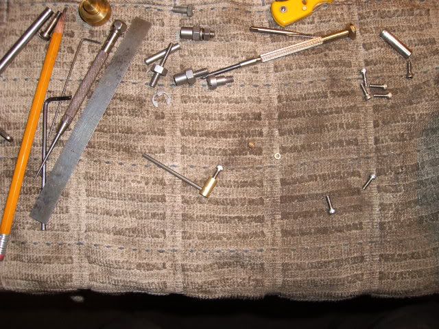
Hi all, getting further along, I don't know why things work out the way they do, Nick, I think the "poppin" works freely because there is almost no friction with regard to the valve, as only the swivelling of the shaft in its bearings, and the slight pressure at the closing of the valve have any real "bearing" on the friction issue.  I know that valve friction is important in the Duclos flame sucker, because I've tried several different valve types and have reverted to the spring pressure bronze plate with the tiny slot as the freeist moving.
   On this engine, I was struck by the nature of some of my scrap, I knew I had a piece of metric ground shafting, small, and with two sintered bronze bushes which came out of a CD player, and I found the box with the scrap from that old player, and the light lit up.  First, I had to get rid of the stainless flywheel, so I got to work on the cast iron one


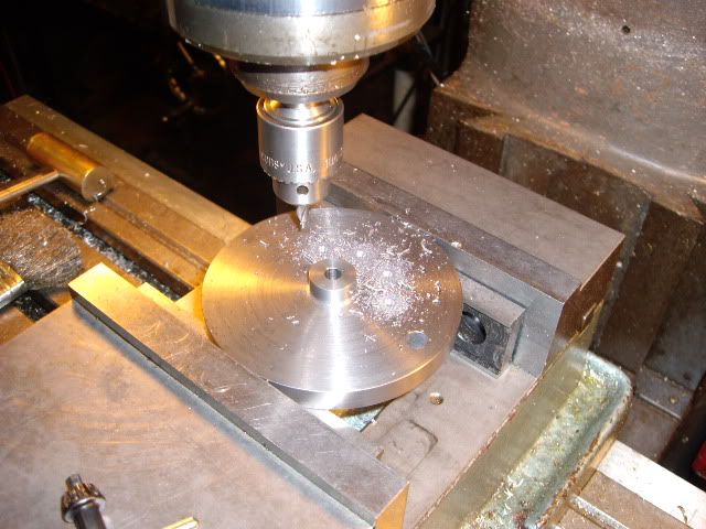
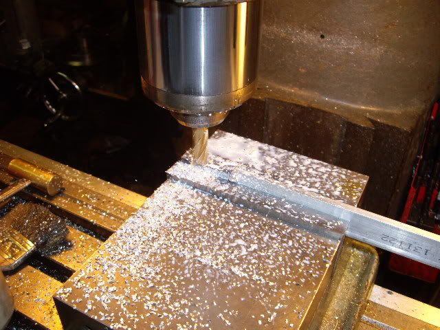
center drilling the iron flywheel for nine holes


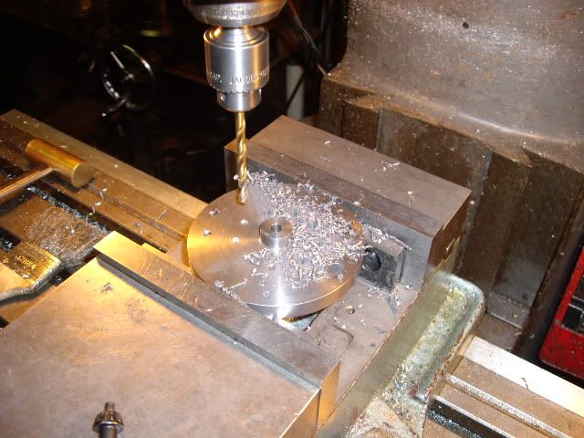
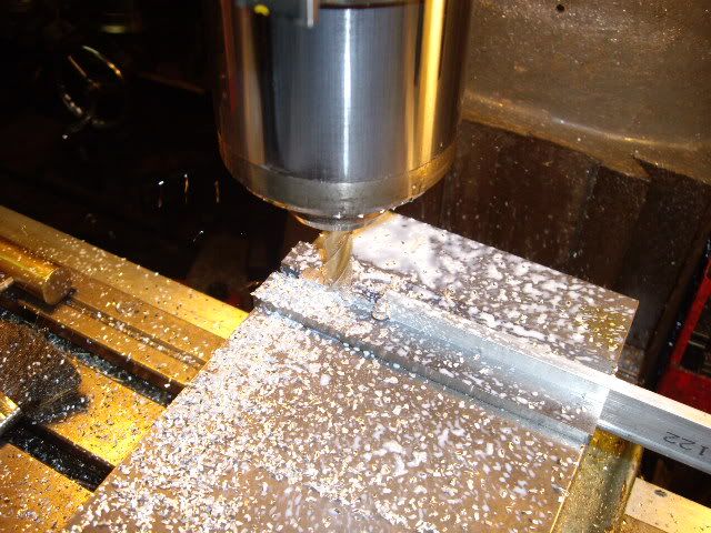
step drilling my way up to size


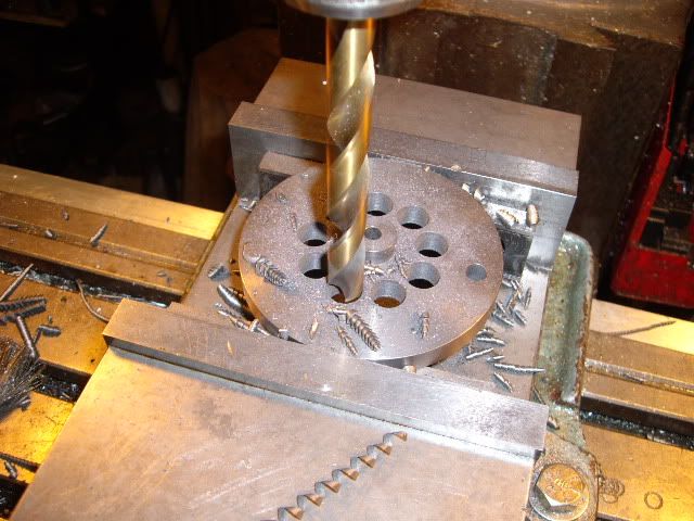
a half inch set of holes is all that would fit where I put them, but it seems like a good flywheel, on just a straight shaft in the main bearings, the flywheel stops at random, so it's pretty well balanced as is


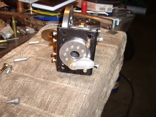
the flywheel in place


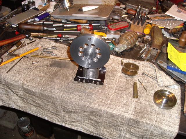
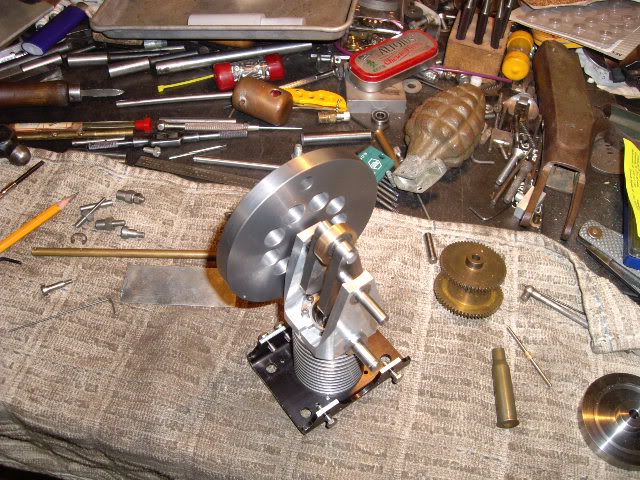
a frontal view of the flywheel on the engine, note the second "extra" hole, put in to balance the hole that was already in the gear.  that 7.62 by 54r casing isn't just there for looks, it is what I used to press the bearings onto the mainshafts, with the pressure entirely on the inner race to keep from damaging the ball bearings


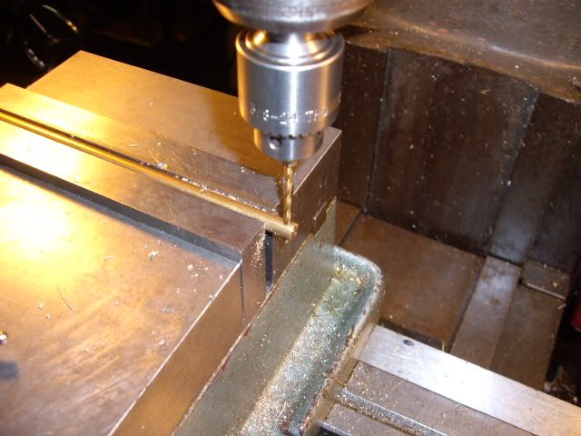
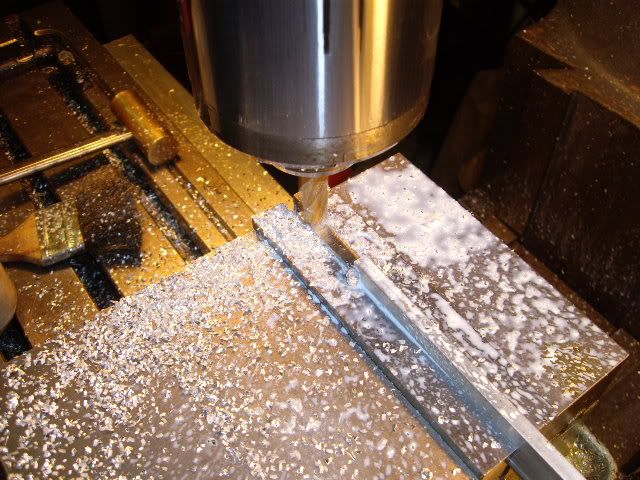
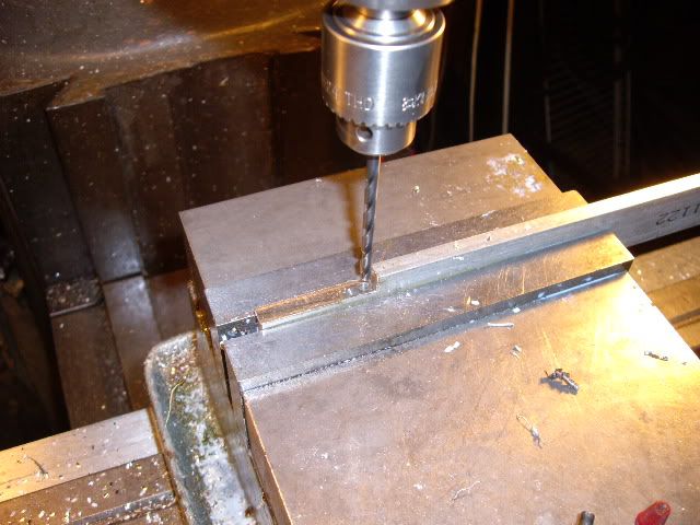
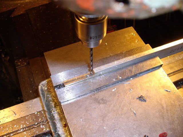
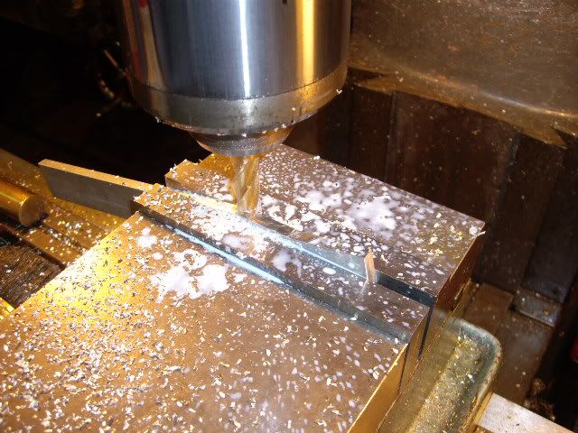
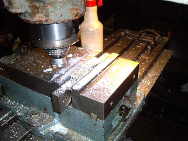
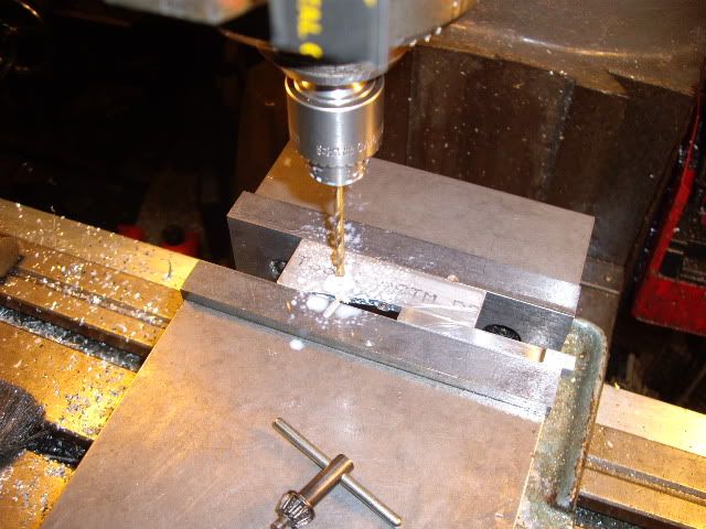
drilling the cross hole in the valve shaft stanchion for the 2.5mm valve shaft, the other cross hole is to the left, in the shaft in the vise jaws


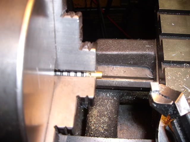
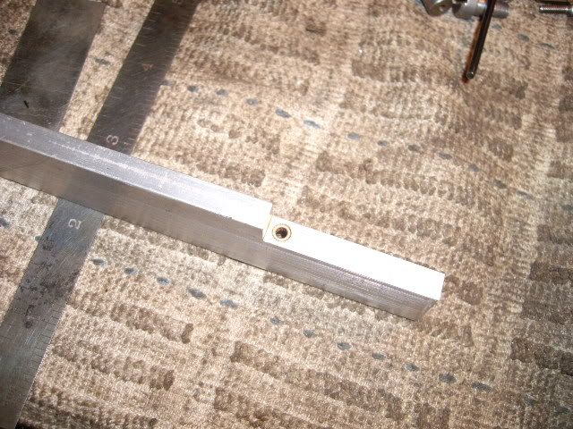
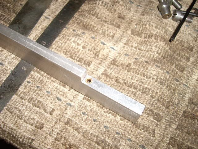
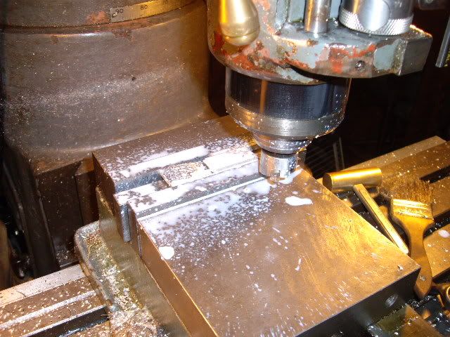
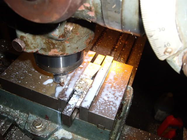
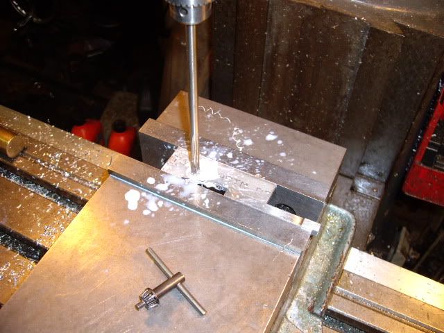
facing off one stanchion to length, measuring from the "bottom" of the shaft hole to the base of the stanchions


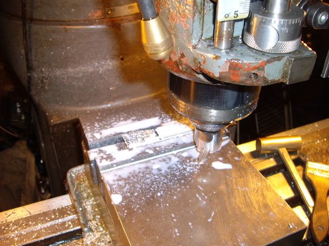
facing off the other to match, both have been drilled and tapped #4-40


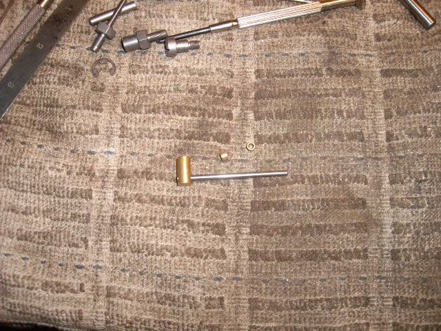
stanchion with valve shaft pressed in place, sintered bushings along side


stanchion and shaft with allen screw in the base of the stanchion


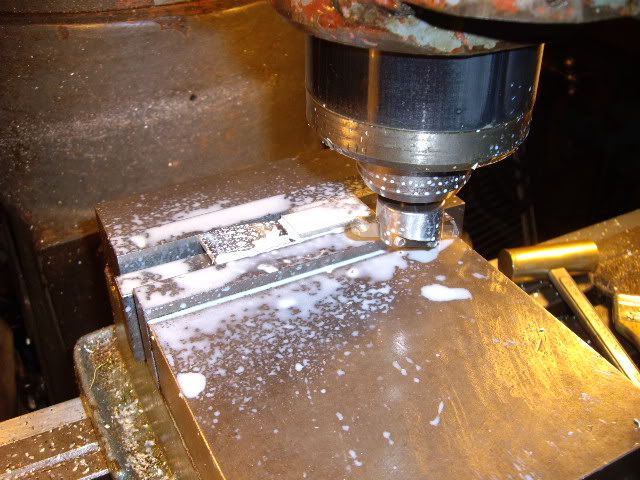
making the valve carrier, narrowing it for clearance


more milling, started with quarter by one inch 6061-T-6 bar, reducing end to 3/4 inch


final cut to size, time for drilling for the valve shaft


after center drilling, drilling through with an undersized hole


no reamer that size, finishing with a sharp drill on size


the valve shaft hole with bushings pushed in place with loctite


another view of the valve shaft bushings


machining clearance in the top of the valve carrier


machining down the carrier, making room for a valve between it and the head


more trimming, with a flycutter, holding the carrier by less than an 1/8th inch in the vise


taking finishing cuts, checking for clearance against the stanchions and head surface for reference


finishing the other side beyond the bushings


final cuts over the bushings, to ensure they clear the head in action as well


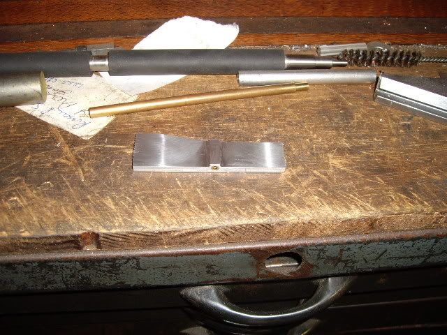
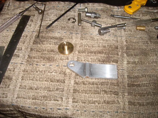
the valve carrier blank


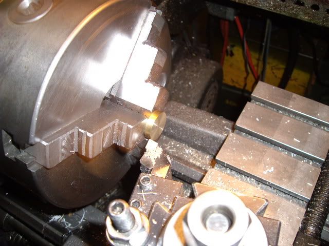
finding a piece of bronze .875 in diameter with a spigot on it, I turned down the spigot to a quarter inch, and chucked on that spigot to face off two thirds of the thickness of the valve


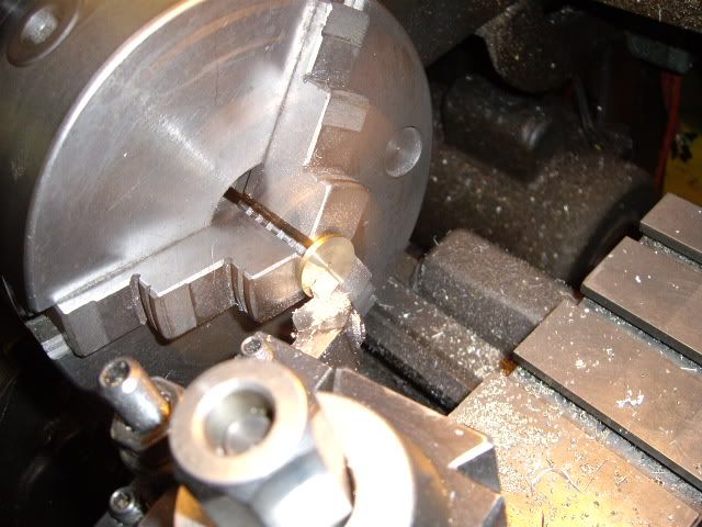
more facing, final thickness will be .090 inches


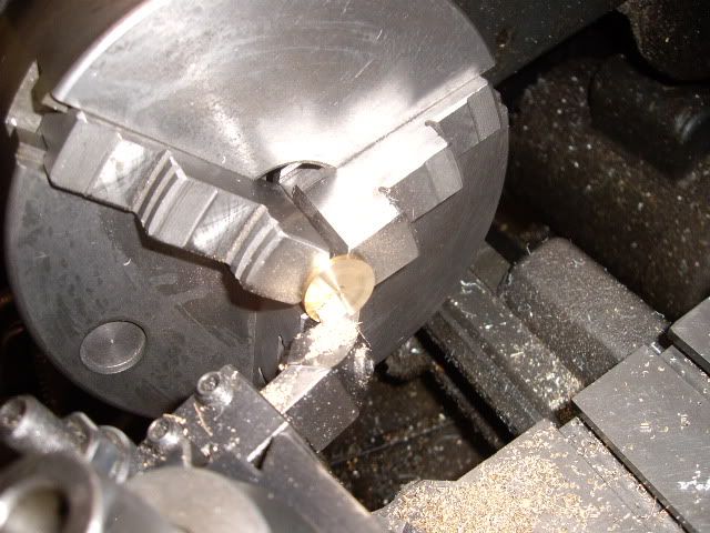
with the valve to size, taking a cut to "hollow" the center to reduce the area of contact leaving a good .200 rim laying flat on the head surface for sealing.  the hollow is about fifteen thousandths deep, just enough to relieve it.


after center drilling on the marked spot, drilling through the valve carrier


with the spigot on the valve turned to .248, reaming the carrier hole at .250


some bandsaw profiling, and filing to a fine finish, the carrier end finished


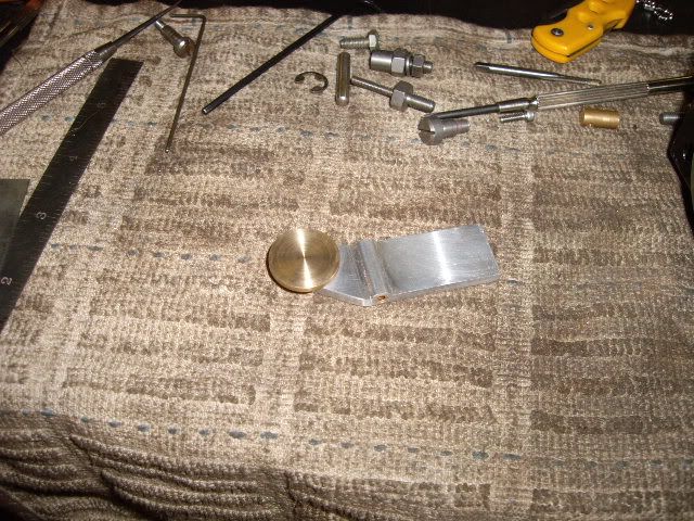
the valve sitting in the carrier


the carrier with the valve, mocked up on the head


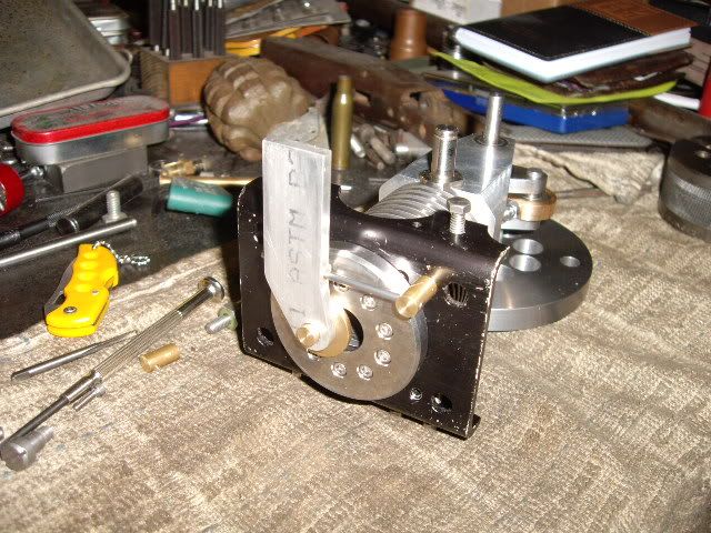
with both stanchions pressed on the valve shaft, with the valve carrier cut to fit, the valve gear fit to the bracket and the valve in place against the head, fitting nicely, freely moving, with a good vacuum seal being the final test.  This wasn't exactly what I thought I was going to do for a valve, but it turned out nicely, and fits well, funny how those lightbulbs sometimes don't exactly end up making parts you thought would be there.  This valve is inspired by Herr Bettinger and his #2 Flammenfresser, which runs too well not to copy from.  Next, I will have to make the operating lever and cam to move the valve in time and space, and maybe look at some sort of frame or something.  Thanks for watching and all the comments, I'm having more fun than a human bean is supposed to  :poke: mad jack  :lol:

Offline NickG

  • Madmodder Committee
  • Hero Member
  • *****
  • Posts: 1890
Re: building a new flame sucker
« Reply #43 on: January 07, 2011, 03:48:08 AM »
Great work as always Madjack, I've never seen a valve like that before but looks a good idea.

What keeps the valve against the port face though? Is it designed to blow off the face as the piston nears TDC and the pressure increases? and what will keep the carrier from pivoting on its shaft, or is it supposed to?

Very intriguing build this.  :bow:

NIck
Location: County Durham (North East England)

Offline sbwhart

  • Global Moderator
  • Hero Member
  • *****
  • Posts: 3530
  • Country: gb
  • Smile, Be Happy, Have Fun and Rock Until you Drop
Re: building a new flame sucker
« Reply #44 on: January 07, 2011, 04:50:06 AM »
Very interesting stuff their Jack is this your own design ?, some great work.

I hope that pineapple isn't live


:D

Can't wait to see it running

Stew
A little bit of clearance never got in the road
 :wave:

Location:- Crewe Cheshire

Offline madjackghengis

  • Hero Member
  • *****
  • Posts: 717
  • big engine
Re: building a new flame sucker
« Reply #45 on: January 07, 2011, 09:23:09 AM »
Hi all, actually Stew, it used to be, but is now inert, but can be revived if'n govment agents start nosing around here abouts.  We don't much like govment agents and revenuers :bugeye:  This kind of valve is sort of like one on Gunther Bettinger's web site bettingue.blogspot.com, but built with the odds and ends I had on hand.  I can't discard a CD player or other piece of mechanical or electrical devise without gutting it for "spare parts", and I feel like I'm recycling at the most efficient level, by re-using parts in their original form for a different purpose.  I knew I had that 2.5mm shaft and two tiny bushes that I broke out of the plastic carriage, and they slide very nicely with just about the right distance for full opening and closing.


The valve carrier needed an extention to meet with the lever and to give both a connection to the actuation lever, which will be a pin through a hole, and a place for a spring to press against, to keep the valve in contact with the head.  I found a spring clip from a pocket knife which had some three tiny #1-56 screws, so the valve carrier got drilled and tapped for the three screws, and the spring clip installed.  It is cut off later, when the lever is in place to give a good place to cut it off at


with a stanchion in place on the crank structure, a bushing is turned to fit over it, with end clearance for the E-clip which will hold the lever in place.  The bushing is turned with a 5/16ths bore, a 1/2 in o.d., and a 7/16ths step and shoulder for the lever to press onto, establishing its place relative to the cam shaft, and the valve carrier.


turning the shoulder on the bushing


cutting off the bushing, I chucked it lightly after cutting off and trimmed it to proper length


the valve lever blank is a piece of 1/4 by one inch 6061, step drilled for the bushing, up to the 7/16ths as I don't have that size reamer, the last two drills were only a fifteen thousandths under and apart, so the hole came out dead on size with the final drill


Once the pivot hole was established, I measured from the pivot to the mainshaft, and eyeballed the offset for the cam roller pin, putting it as close to the edge as good engineering allows.  The roller is a bearing with a 3/16ths i.d., and a 1/2 in o.d.  The pin is a rod bearing roller from a Harley rod loose bearing set, .0002 oversized, for a press fit.


once the holes were in place, I cut off the excess with my bandsaw, and filed to a fine finish.  The valve end is still to be cut to length, a pin put in the end, to fit in a hole to be drilled in the valve carrier extention, and a small coil spring on the pin to provide pressure on the end of that extention, and keep the valve face against the head, while the valve moves.  The end of the arm needs enough cut off to make room for the spring, with the end milled flat to be drilled for a pin about 3/4 in long to both move the valve, and carry the coil spring.


the almost completed valve operating lever with bushing and cam follower bearing in place


the valve lever in place on the engine


a side view of the lever in place.  Now that this is done, I can calculate where the pin must go in the lever, where the hole in the valve carrier extention must go to match the pin, and then turn a cam with provisions for adjusting valve opening and timing, an adjustable cam if you will.  Not to be confused with the variable cam timing put in Nick's car, which seems to be a really bugger of a problem.  Hopefully this answered some questions, and opened up some new questions, one can at least hope  :poke: :lol: mad jack

Offline winklmj

  • Jr. Member
  • **
  • Posts: 56
  • Country: us
Re: building a new flame sucker
« Reply #46 on: January 07, 2011, 10:43:11 AM »
I hope that pineapple isn't live

Will be used only if the engine doesn't run.
Mike

Offline Stilldrillin

  • Global Moderator
  • Hero Member
  • *****
  • Posts: 4972
  • Country: gb
  • Staveley, Derbyshire. England.
Re: building a new flame sucker
« Reply #47 on: January 07, 2011, 12:10:41 PM »
Your last post answered several unasked questions Jack!  :scratch:

You're doin' well. Keep on doin!  :thumbup:

David D
David.

Still drilling holes... Sometimes, in the right place!

Still modifying bits of metal... Occasionally, making an improvement!

Offline cidrontmg

  • Full Member
  • ***
  • Posts: 229
  • Country: pt
Re: building a new flame sucker
« Reply #48 on: January 07, 2011, 01:02:55 PM »
Coming together fine. I have not yet figured out which way it will stand when finished. That is, if it will be (cylinder) horizontal or vertical. Or at some angle. But the pieces look like they mean business! Sturdy and to the purpose, the way I'd like to build my engines  :med: It's not missing much before the first smoke.
 :wave:
Olli
Penafiel
Portugal

Rob.Wilson

  • Guest
Re: building a new flame sucker
« Reply #49 on: January 07, 2011, 01:30:45 PM »
Hi Jack

Watching this build with allot of interest  ,,,,,,,,, great  stuff  :thumbup:

Rob


Were dose the hand grenade go  :scratch: