Author Topic: Solenoid engine Build  (Read 64406 times)

Offline CallMeAl

  • Jr. Member
  • **
  • Posts: 95
  • I came, I saw, I wondered how to do it!
Re: Solenoid engine Build
« Reply #25 on: March 02, 2011, 12:21:46 AM »
As mentioned above I was out of town last week and didn't get much done on the solenoid engine.  Started working on the cross head:

Squared up a block and drilled and reamed holes


Trimmed the piston rod for length and fitted to cross head and milled connecting rod clevis ears:


Cross head on engine. Slides very smoothly and keeps piston from rubbing the walls on the solenoid tube


I still need to radius the corners and make it look all fancy and such!

Moving along slowly.
I skin cats my own way!

Offline CallMeAl

  • Jr. Member
  • **
  • Posts: 95
  • I came, I saw, I wondered how to do it!
Re: Solenoid engine Build
« Reply #26 on: May 24, 2011, 10:09:10 PM »
Finally getting back to working on this project.  I have been busy with other stuff - Spring, ya know. Plowed out the cavity for the crank weights.


Leveled area for bearing caps.


Made bearing caps, line drilled and bored the bushings and reamed them in place.


Test fitted the fly wheel, as you can see, a barbell weight I found at he scrap yard and have been determined to use it some where!

I know:  :loco:


Pressed the crank together with a little Loctite - twice.  I'm not totally happy with the result, but I'm going to carry on so I can make some progress on this motor.


Test mounted the previously made ball governor just see how it looked.. The scale doesn't look quite right, but this is a learning/ experimental project so many lessons are being gained. It's somewhat intimidating the skill level on the members on this site and though I have learned much by looking over the shoulders of the master builders here, my techniques need much practice and improvement.  I need to improve on my measurement precision to approach the quality of projects presented here.  I have built 3 previous engines, each very different from the others, and learned something from each - this one is no exception!


This may be why I never build anything off of published plans, this way I can go my own way and fudge thing as I need too! ::)

Thanks for viewing.
I skin cats my own way!

Offline saw

  • Hero Member
  • *****
  • Posts: 1003
  • Country: se
  • lucky amateur
    • Svenssons AckordsWerkstad
Re: Solenoid engine Build
« Reply #27 on: May 25, 2011, 04:22:58 AM »
Very nice build.  :clap: :thumbup:
_________________________
Greetings / Benni
http://myprojecty.wordpress.com/category/steam-engine/

Offline Stilldrillin

  • Global Moderator
  • Hero Member
  • *****
  • Posts: 4972
  • Country: gb
  • Staveley, Derbyshire. England.
Re: Solenoid engine Build
« Reply #28 on: May 25, 2011, 10:10:40 AM »
That engine is developing so nicely......   :bugeye:

Love it! Well done/ doing, Al!  :clap: :thumbup:

David D
David.

Still drilling holes... Sometimes, in the right place!

Still modifying bits of metal... Occasionally, making an improvement!

Offline cfellows

  • In Memoriam
  • Sr. Member
  • *****
  • Posts: 303
Re: Solenoid engine Build
« Reply #29 on: May 25, 2011, 11:15:04 AM »
You've got some nice features on this engine, Al.  I like the crosshead arrangement, it's integrated into the frame very nicely.  Do you know what the voltage and amp rating of the solenoid are?

Chuck

Offline CallMeAl

  • Jr. Member
  • **
  • Posts: 95
  • I came, I saw, I wondered how to do it!
Re: Solenoid engine Build
« Reply #30 on: May 25, 2011, 10:17:00 PM »
Thanks for the comment Saw and David.

Chuck:  The solenoid is rated a 110V AC about 5A.  My intention is to be able to plug it to run it.  I know enough about electricity to be dangerous and have tried the coil with a 14.4V DC drill battery and it pulled the piston in with a lot of force.  I may see if it works on DC, but that may cause some heating issues in the coil and arcing in the switches.
I skin cats my own way!

Offline metalmad

  • Jr. Member
  • **
  • Posts: 62
Re: Solenoid engine Build
« Reply #31 on: May 26, 2011, 02:23:50 AM »
hay Mate
Ive never seen a solenoid motor before but yours is looking great
Pete :clap:
A little bit every day, sometimes the same little bit!

Offline cfellows

  • In Memoriam
  • Sr. Member
  • *****
  • Posts: 303
Re: Solenoid engine Build
« Reply #32 on: May 26, 2011, 07:00:24 PM »
Thanks for the comment Saw and David.

Chuck:  The solenoid is rated a 110V AC about 5A.  My intention is to be able to plug it to run it.  I know enough about electricity to be dangerous and have tried the coil with a 14.4V DC drill battery and it pulled the piston in with a lot of force.  I may see if it works on DC, but that may cause some heating issues in the coil and arcing in the switches.

Since you are running in hit n miss mode, you could run the solenoid at a lot higher voltage / amperage.  That would give you more of a power stroke giving you more RPM's between "hits".  You can limit arcing at the switch by installing a clamping diode if you are using DC.

Chuck

Offline CallMeAl

  • Jr. Member
  • **
  • Posts: 95
  • I came, I saw, I wondered how to do it!
Re: Solenoid engine Build
« Reply #33 on: May 29, 2011, 11:11:06 PM »
Pete: The rate I'm going on this you still might not ever see a solenoid motor!  Thanks for your comment.

Chuck:  I'm fairly sure this is going to be a 110V motor.  I have yet to figure out the "valving" but I have a idea of how I want to do it and I hope I can "tune" it in to make this thing actually work!  :zap:
I skin cats my own way!

Offline CallMeAl

  • Jr. Member
  • **
  • Posts: 95
  • I came, I saw, I wondered how to do it!
Re: Solenoid engine Build
« Reply #34 on: May 29, 2011, 11:53:29 PM »
Now that I have a crank and the cross head, I wanted to try a different way, at least to me, to make a connecting rod to hook the two together.  Started with a aluminum block and knocked the lead corners of with a ball mill and drilled a hole for the rod shaft.


Turned down a piece of 1/2" bar to 3/8" on the end with my shop built tangential lathe tool holder, this will be held in the base with a set screw and some Locktite when finished.


Tapered the rod, but left the end to cut for a the small end of the rod.


Here is a couple of shots of the tool holder and bit.  It doesn't do everything, but it cuts well, is easy to sharpen when you make the simple bit sharpening guide, and with the length of bit I have in it and how often I need to sharpen it the bit will out last me most likely!


I drilled the base end for bolts, cut the end off for a cap, reinstalled the cap piece, drilled and reamed for the pin, and finally turned a clearance shoulder on the sides.


Next was to drill the cross hole in the small end and flatten the sides.  Rod assembled.


Rod installed on the motor.  After a little tuning, it operated smoothly.


Now that the major mechanical components are in place, I will have to figure out the "valving" arrangement and actuation.

Thanks for viewing.


I skin cats my own way!

Rob.Wilson

  • Guest
Re: Solenoid engine Build
« Reply #35 on: May 30, 2011, 04:13:33 AM »
 :clap: :clap: :clap: :clap: :clap: Nice going Al  :dremel:

The engine is coming together great  :thumbup:


Rob

Offline CallMeAl

  • Jr. Member
  • **
  • Posts: 95
  • I came, I saw, I wondered how to do it!
Re: Solenoid engine Build
« Reply #36 on: June 01, 2011, 12:16:12 AM »
Thanks Rob.  I value a comment from from someone with our abilities.  :bow:
I skin cats my own way!

Offline CallMeAl

  • Jr. Member
  • **
  • Posts: 95
  • I came, I saw, I wondered how to do it!
Re: Solenoid engine Build
« Reply #37 on: July 12, 2011, 10:24:49 PM »
Time to put a bullet the head of this thread/project and put it out of it's misery.  Lot of things have happened since I posted last. Most of them discouraging.  Here are the finial steps of putting this experimental engine/motor and the frustrating end.

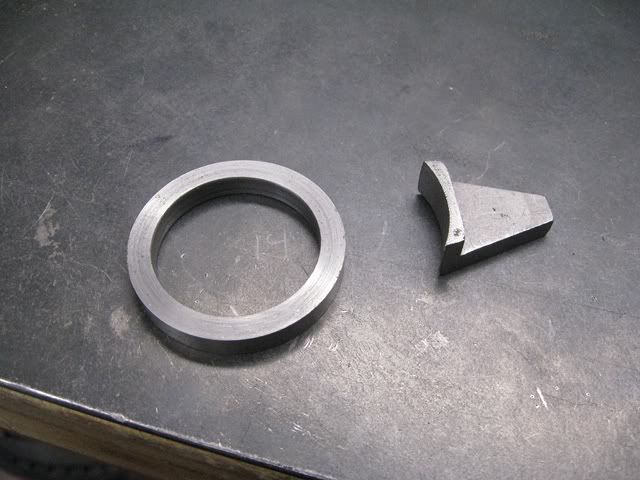
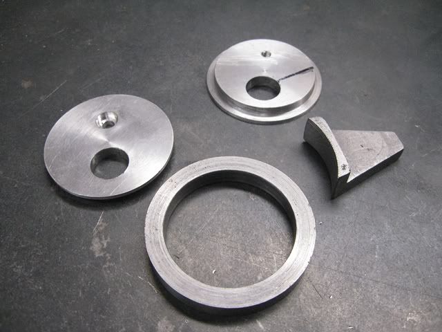
Making the eccentric:


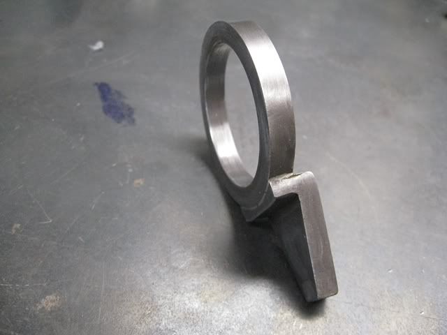
Soldered together showing the offset:


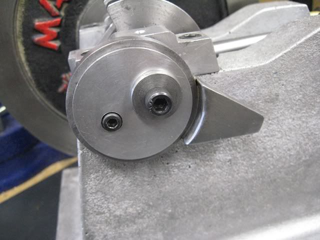
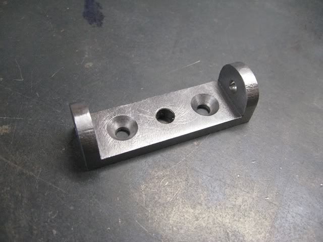
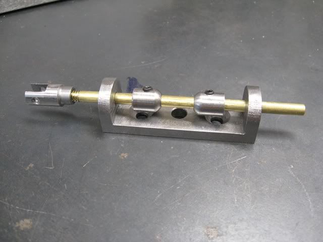
Switch rod guide bracket and actuating cams:


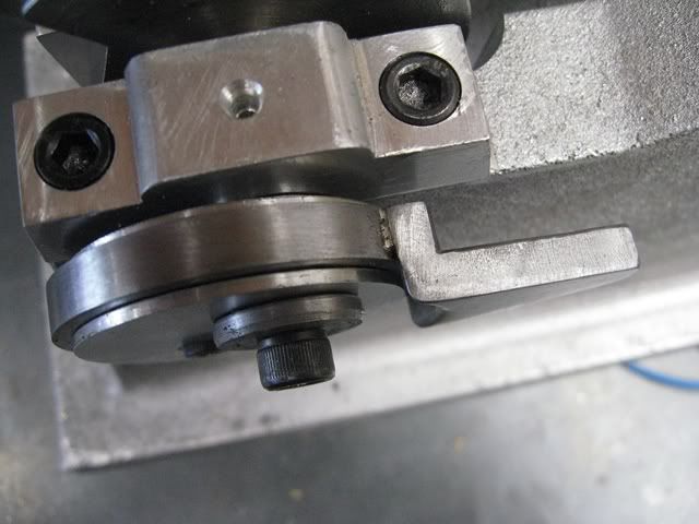
Mounted on the frame:


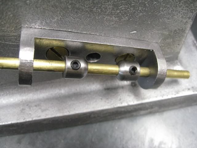
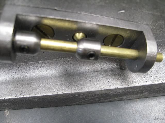
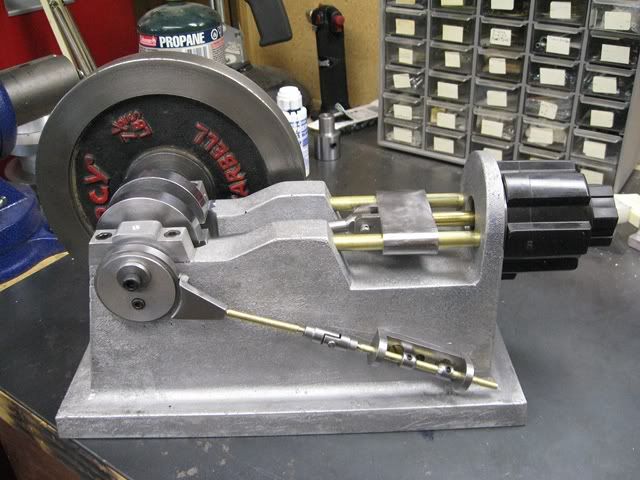
Switch actuator rod and how it is actuated by the cams:


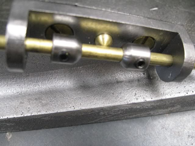
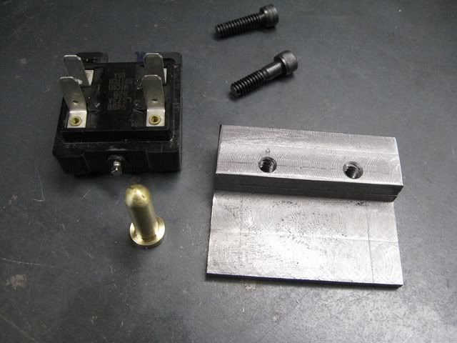
Switch bracket and it's mounting in the base.  The switch was out of an industrial limit switch and has a spring loaded plunger:


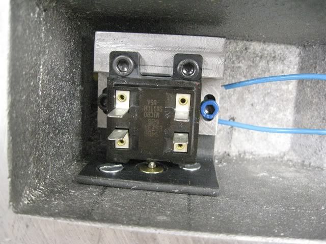
The overall arrangement of the switching setup:


Looks like it might work, but here is the result:


I have spent a lot of time trying to get this running, but no combination of eccentric and cam timing can make it continue to run.  I believe there is just too much friction on the crank bushings and connecting rod to allow the momentum of the fly wheel to continue the rotation.  Also. the impulse from the coil is not strong enough and it starts heating up more than I would like (I expected this might happen, but not as quickly as it does).

I have reached that point where I must give up on this configuration, redo the bearings, or convert the bones into a pneumatic engine, which what is most likely to happen.

Oh well, not everything turns out like you would hope of expect it might.  I learned something form this exercise that will be useful on the next project.  Time to put this one on the shelf for a while and comptenplate the adventure in self taught home shop machining!

 :D

I want to thank all that all that followed along on this episode and I certainly enjoyed your comments and encouragement.  :clap:

Sorry the end turned out kind of anticlimactic!

I skin cats my own way!

Offline John Hill

  • The Artful Bodger
  • Madmodder Committee
  • Hero Member
  • *****
  • Posts: 2016
  • Country: nz
Re: Solenoid engine Build
« Reply #38 on: July 12, 2011, 11:23:01 PM »
Dont give up on it yet!

I see you said the solenoid is 110Volts 5Amps.

I would be inclined to charge a big capacitor via a diode and current limiting resistor.  The capacitor will charge to much more than 110V and if you use a simple voltage doubling arrangement you will have several hundred volts available to be dumped into the solenoid in a very short, very high current, pulse. You could add capacitors for a longer pulse and hence more torque.  Those are my ideas anyway. :beer:
From the den of The Artful Bodger

Offline Mad_Grasshopper

  • Jr. Member
  • **
  • Posts: 7
  • Faceting Machine
Re: Solenoid engine Build
« Reply #39 on: July 13, 2011, 02:09:27 PM »
I don't understand the timing. :scratch: It appears to me to be flowing current twice per revolution when it should only activate once at a few degrees after TDC. -Unless there is something I don't see switching the current from push to pull? Has it been tried with only one of the collar-ramps engaging switch? Looks too cool to quit now!

Regards,
Jamie

Offline John Hill

  • The Artful Bodger
  • Madmodder Committee
  • Hero Member
  • *****
  • Posts: 2016
  • Country: nz
Re: Solenoid engine Build
« Reply #40 on: July 13, 2011, 03:46:25 PM »
OK, after laying awake trying to figure out why this does not run as nicely as it looks I might have figured something..

That solenoid is an AC device?  If so it is quite different in operating principle to a regular DC solenoid. 

The AC solenoid operates on the same principle as a split phase AC motor so you should probably ignore my earlier comment about giving it a vigorous DC kick.

However that still does not explain why it does not work. 
John
From the den of The Artful Bodger

Rob.Wilson

  • Guest
Re: Solenoid engine Build
« Reply #41 on: July 13, 2011, 05:13:41 PM »
Al ,,,,,,,,,, Still a great thread whatever the out come  :clap: :clap: :clap: :clap:   i am sure you will get that cat skinned  :med:


Rob  :thumbup:

Offline cfellows

  • In Memoriam
  • Sr. Member
  • *****
  • Posts: 303
Re: Solenoid engine Build
« Reply #42 on: July 13, 2011, 11:22:21 PM »
If that is a typical solenoid, the switch should close at or shortly after bottom dead center then open at or shortly before top dead center.  Does your switch open or close when the cams push against the button?

Chuck

Offline Stilldrillin

  • Global Moderator
  • Hero Member
  • *****
  • Posts: 4972
  • Country: gb
  • Staveley, Derbyshire. England.
Re: Solenoid engine Build
« Reply #43 on: July 14, 2011, 02:09:48 AM »
I don't understand the timing. :scratch: It appears to me to be flowing current twice per revolution when it should only activate once at a few degrees after TDC. -Unless there is something I don't see switching the current from push to pull? Has it been tried with only one of the collar-ramps engaging switch? Looks too cool to quit now!

Regards,
Jamie


Al. I'm with Jamie on this one......
At the final crank rotation....... The solenoid "squarks" at both ends of the stroke.......

Or, am I missing something.......  :scratch:

What a crackin' build.  :clap: :clap:    Please don't abandon at this point.......   :palm:

David D

David.

Still drilling holes... Sometimes, in the right place!

Still modifying bits of metal... Occasionally, making an improvement!

Offline tomrux

  • Jr. Member
  • **
  • Posts: 34
Re: Solenoid engine Build
« Reply #44 on: July 14, 2011, 04:39:30 AM »
I dont have a whole lot of experience building motors yet (planing on fixing that once i get a couple of other projects out of the way) but do have abit more than the usual electric/electronic  knowhow.

an ac solenoid will only work in one direction (usually pull) reversing a dc curentthrough it wont change that. try using a small spring for one direction (I would start with push)and electric excitation for the other(pull). the idea of using capacitors to more grunt is a good one but would need to be fairly big.

Tom

Offline SPiN Racing

  • Madmodder Committee
  • Hero Member
  • *****
  • Posts: 506
Re: Solenoid engine Build
« Reply #45 on: July 14, 2011, 10:12:51 AM »
Beautiful build, and exciting project!

I was a arcade manager in the late 80s, and early 90s when in college and a bit beyond, and ended up traveling all over ehe state of Florida repairing pinball machines for the arcade company I worked for.

I still have a handful of the Solenoids we used to use for pinball machines, and seeing this made me seriously consider putting one of these on the back burner.

I actuallymade a electromagnetic rail gun of sorts from coils back then.  Basically it was a board with 8 coils in a line, wired with optical switches, so that when the metal shaft broke the optical sensor the next coil in line was energized, and drew the rod into it. When the rod passed far enough into it, the coil turned off and inertia carried it through to break the beam on the next coil, energizing it.

In the end it would shoot the rod that was attached to the pinball flippers across the arcade with enough force to stick it into the cedar 1" paneling 30 feet away.


With regard to your engine, as others have mentioned it sounds as if its energizing whenever the piston is anything OTHER than TDC.

I would think you simply need to set up a relay that closes when the engine is at BDC, and then once it hits TDC, or a bit before, it Disengages the relay.. so the coil is no longer energized while its traveling to BDC.

Scott
SPiN Racing

Offline AdeV

  • Madmodder Committee
  • Hero Member
  • *****
  • Posts: 2434
  • Country: gb
Re: Solenoid engine Build
« Reply #46 on: July 14, 2011, 10:58:31 AM »
Firstly - congratulations on a beautifully built machine! You've got some excellent skills there, many of them I'd like to learn myself...

So, have some of these:  :bow: :bow: :bow: :beer:  :thumbup: :clap:

A thought as to why it's not running:

Your activation system is turning the solenoid on both as the piston is going down into the solenoid, and as it is pushed back out; ISTM that the solenoid is doing its best to stop the engine on the in stroke; and obviously can't push hard enough to overcome both that & the friction on the out stroke. Since your net energy input from the solenoid is, effectively, zero; what you're seeing is the energy imparted to the flywheel being lost to friction.

IMHO you need to alter your activation system so it doesn't "fire" on the side-shaft down-stroke (piston in-stroke). I can think of 2 ways to do this:

1) Profile a bar so that one side allows the switch to operate, the other side doesn't. at the end of each stroke, have a mechanism that causes the bar to turn by 90 degrees, anticlock at one end, clock at the other; so the bar presents a different profile each stroke (but the same profile each up stroke & the same profile each downstroke). If it's as difficult to machine as it is to describe, it's probably quite a tricky one.... OTOH, it gives you a way of hooking your governer up; if the engine is above the governer shut-off speed, the bar-twisting mechanism is moved out of reach; so the "non active" side of the bar is always presented to the engine; as it slows, the twister drops back into place, allowing the solenoid to "fire" again.


2) Arrange the switch shaft to travel at half the speed of the crank shaft, just like a real IC engine camshaft does. You'll still need to find some way of making it "fire" at different points on the up & down stroke (of the side shaft), though...
Cheers!
Ade.
--
Location: Wallasey, Merseyside. A long way from anywhere.
Occasionally: Zhengzhou, China. An even longer way from anywhere...

Offline DaveH

  • Hero Member
  • *****
  • Posts: 1413
  • Country: za
  • Kempton Park, South Africa
Re: Solenoid engine Build
« Reply #47 on: July 14, 2011, 12:59:06 PM »
Al,

what a great post. :clap:

Beautifully built engine .... incorporating great skill coupled with a lot of know how. :clap: :clap: :clap:

Thanks Al I really enjoyed it. :D

 :beer:
DaveH
(Ex Leicester, Thurmaston, Ashby De La Zouch.)

Offline CallMeAl

  • Jr. Member
  • **
  • Posts: 95
  • I came, I saw, I wondered how to do it!
Re: Solenoid engine Build
« Reply #48 on: July 15, 2011, 12:20:19 AM »
First of all, thanks everyone for your comments and words of encouragement.  Sorry for the slow reply, but I have distant family in town and an somewhat occupied for a few days.

I appreciate the suggestions and advice on how I might over come the problems with the design on the switching on this motor.

Some answers to questions:

cfellows: the cams close the switch. 

Jamie & David D: Yes, it fires at each end of the stroke for I am trying to an impulse at each end of the stroke (double acting).  I'll elaborate on my thinking in another post later in the next couple of days.  Unfortunately the cams currently are actuating the switch just prior to TDC and BDC so I was hoping the momentum of a heavy flywheel would carry the piston over center and the coil impulse would pull it back until the cam released the switch.  Hey, i said it was experimental! :loco:

 AbeV:  Interesting suggestions

John Hill: When I started this I stated I new enough about electricity to be dangerous  :zap: and I still stand by that statement. 

Rob & DaveH: Thanks for your nice comments.

Scott & Tom:  As I said, I will try to explain my thinking on the solenoid, piston, switch arrangement in a following post, thanks for your interest.

I'm going to play around more with the timing on this thing this weekend and try a couple of other things before I totally give up on this thing, but not too long for I have another project in mind and am itching to get on with it.

I skin cats my own way!

Offline John Hill

  • The Artful Bodger
  • Madmodder Committee
  • Hero Member
  • *****
  • Posts: 2016
  • Country: nz
Re: Solenoid engine Build
« Reply #49 on: July 15, 2011, 02:02:53 AM »
Al,  unfortunately I dont think you can get double action from an AC solenoid.

My suggestion is to adjust your timing so that the switch is closed for the entire 'in stroke',  that would be the most simple configuration and would be a good starting point.  IMHO of course.
From the den of The Artful Bodger