Author Topic: Another 4" CNC rotary table  (Read 57968 times)

Offline j45on

  • Sr. Member
  • ****
  • Posts: 380
  • My tiny workshop Location Ashford Kent
Another 4" CNC rotary table
« on: October 14, 2010, 06:59:42 PM »
I'm not sure this really warrants a new topic as I shall be shamelessly copying Craynerds stepper mounting and using Kwackers plans for the electronics  :bow:
Maybe I will detail the building of the electronic bits instead of what has already been done.
But it will be a good place to ask daft questions without filling up other peoples project logs  ::)
I know  :worthless: but until postie delivers my bits there is nothing to show

So far I have ordered the LCD display , 10Mhz crystal , 7805 5V DC Voltage Regulator , Microchip PIC18F452-I/P and a 40 pin dip socket
Well apart from the lcd I bought a few of each incase I cock something up  :zap:

I already have copper pcb , ferric chloride , toner transfer stuff and loads of resistors capacitors and possibly the diodes

The main bits I'm confused about are which stepper and controller ? to get.
For the controller It would be nice if I can find something to fit in the case along with the rest of the electronics DIY from plans or a kit would be good as well
And the stepper I don't want something huge hanging off my poor little mill but I would like to do some light milling as well so I'm unsure of torque requirements  :scratch:
Would the the stepper at the top of Arc Euro's page be to small ? http://www.arceurotrade.co.uk/Catalogue/Stepper-Motors/Stepper-Motors

I would also like to power the whole lot from my old laptop psu it outputs 19.5 volts 6.7A 130W this should this be enough right ?
Jason

Offline Bluechip

  • Madmodder Committee
  • Hero Member
  • *****
  • Posts: 1513
  • Country: england
  • Derbyshire UK
Re: Another 4" CNC rotary table
« Reply #1 on: October 14, 2010, 07:34:47 PM »
Jason

Just an observation.

Some SMPS power supplies don't like transient loads like steppers on them.

You can get the output voltage collapsing to a low value momentarily. ie a nominal 12V dropping to some 6V or so for several hundred uSecs.

Try your PSU if it is otherwise suitable . If you get mis-stepping, you might need to scope the PSU output before you look elsewhere.

Dave BC

 
I have a few modest talents. Knowing what I'm doing isn't one of them.

Offline Brass_Machine

  • Administrator
  • Hero Member
  • *****
  • Posts: 5504
  • Country: us
Re: Another 4" CNC rotary table
« Reply #2 on: October 14, 2010, 08:38:14 PM »
Absolutely it deserves its own thread. Please post away!

Eric
Science is fun.

We're all mad here. I'm mad. You're mad.

Offline spuddevans

  • Global Moderator
  • Hero Member
  • *****
  • Posts: 1618
  • Country: 00
  • Portadown, Northern Ireland
    • My Photo website
Re: Another 4" CNC rotary table
« Reply #3 on: October 15, 2010, 03:43:24 AM »
Some SMPS power supplies don't like transient loads like steppers on them.

You can get the output voltage collapsing to a low value momentarily. ie a nominal 12V dropping to some 6V or so for several hundred uSecs.

Very true, but isnt that why god created 10,000uF capacitors :thumbup:

 Just bung a couple of 10000uF caps in parallel, or maybe just one if you are only driving one stepper motor and that should smooth out any of the voltage "dipping" effect that Dave was talking about.


Tim
Measure with a micrometer, mark with chalk, cut with an axe  -  MI0TME

Offline Bluechip

  • Madmodder Committee
  • Hero Member
  • *****
  • Posts: 1513
  • Country: england
  • Derbyshire UK
Re: Another 4" CNC rotary table
« Reply #4 on: October 15, 2010, 03:55:05 AM »
Tim

Yup, my first weapon of choice. A 33,000 uF Sprague Compulytic.

As ever, the Gods crapped upon me, the PSU would not fire up, 'cos it thought it had a s/cct on the output. ATX PSU btw.

So, nothing daunted, to 'prove' I got two wacking great stud diodes. Ran the contraption from the psu through one, and a 12V 40 Ah SLA through t'other.

Fault fixed. Eventually made the geezer a grunty LINEAR. ( T'was not my cnc thingy-wotsit ). I just got involved through a mate.

Dont do cnc. I can effectively make scrap manually. No need to automate.  :thumbup:

Dave BC
I have a few modest talents. Knowing what I'm doing isn't one of them.

Offline raynerd

  • Madmodder Committee
  • Hero Member
  • *****
  • Posts: 2893
  • Country: gb
    • Raynerds Projects - Raynerd.co.uk
Re: Another 4" CNC rotary table
« Reply #5 on: October 15, 2010, 05:41:59 AM »
J45son

Others on here will tell you much more valuble info but if it is any help.

I used the 4.2A (?) or whatever it is, smallest Arc Euro stepper. I was a tight fisted sod and purchased a cheap one from ebay china, a cheapish one from Routout CNC and I managed to kill  :zap: the ebay one for NO reason at all and I made an error and frazzled the Routout. OK, so the Routout one wasn`t of its own fault but the two Arc Euro ones I have have always been nothing short of perfect.

I think my stepper driver is set short of 2A and has plenty of torque to do some light milling. Infact I milled a nice edge with a ball nose onto the cap end of my 10V cylinder cover a few nights back with no problems - light cuts mind you! I think my motor is a Nema 23 of 190 Ncm.

I run it all using ~18V laptop charger, I think Kwacks controller has a regulator in for the 5v for the chip, so I simply run the 18V to the stepper driver and the controller. The other advantage of the Arc Euro driver is that it has a built in voltage regulator, I`m pretty sure for the other two you have to make your own voltage regulator and supply the driver with 5v and obviously the drivers motor connections with the full.

I`m sure others will chime in with more useful info but that is how mine works and I`ve had no probs for nearly a year now and has always been perfect.
« Last Edit: October 15, 2010, 05:44:32 AM by craynerd »

Offline kwackers

  • Sr. Member
  • ****
  • Posts: 356
Re: Another 4" CNC rotary table
« Reply #6 on: October 15, 2010, 06:12:31 AM »
J45son

and I made an error and frazzled the Routout.
Error?
 :lol:
I shook half a pound of swarf out of its electronics!


Lesson #1: Box.
Put the electronics somewhere nice, they don't like water and they most definitely don't like swarf!  :doh:

Offline raynerd

  • Madmodder Committee
  • Hero Member
  • *****
  • Posts: 2893
  • Country: gb
    • Raynerds Projects - Raynerd.co.uk
Re: Another 4" CNC rotary table
« Reply #7 on: October 15, 2010, 08:07:11 AM »
sh1t - forgot you looked at it for me  :bang:    OK, it was swarf ... well who was I to know that little shards of metal would short out connections!  :ddb:

Offline kwackers

  • Sr. Member
  • ****
  • Posts: 356
Re: Another 4" CNC rotary table
« Reply #8 on: October 15, 2010, 03:21:14 PM »
@j45on

The stepper you've linked to may well be fine, it's only cheap and the mounting is the same as the larger stepper anyway.

Assuming you want to try and keep the size and weight down then what I'd do is buy a driver capable of driving the bigger motor (2.5A), buy the smaller motor and simply set the driver to 1A to drive it.

If it doesn't work then eBay it and buy the bigger one - it'll be a straight swap, just that it'll stick out more.

Worth bearing in mind the intermittent nature of dividing too, which means you could try being naughty and simply crank up the current on the small motor, it'll shorten it's life but given how little work they actually do as dividers I doubt that will be much of an issue. (You won't get the same torque as the big motor though - even at the same current).
(Should point out I'm only guessing at this entire last paragraph - I've never tried it).

With regards the laptop PSU, I've used several for various projects and never had an issue.
If you do have an issue then the large capacitor will fix it and the problem of the PSU shutting down can be gotten round by a resistor in series with the power to the capacitor - this will limit the current to it. The resistor can then be 'shorted out' once the capacitor has charged either manually with a switch or by a 555 based timer and relay.

(You may even find that simply putting the capacitor in series with a resistor calculated for max PSU current and putting them across the supply might be enough to get round any issues with the PSU. Obviously a bit more 'lossy' than switching out the resistor though.)

« Last Edit: October 15, 2010, 03:23:13 PM by kwackers »

Offline j45on

  • Sr. Member
  • ****
  • Posts: 380
  • My tiny workshop Location Ashford Kent
Re: Another 4" CNC rotary table
« Reply #9 on: October 15, 2010, 04:35:39 PM »
Some bits turned up today


I'm going to crack on with etching a board tomorow  :hammer: and must take lots of pics

Thanks for all the tips and info  :thumbup: the big purchases like the stepper and driver will have to wait until I get paid which is luckily when ARC re open after the midlands show

I have a few questions  :scratch:
The 8 pin SIL socket for the keyboard ,all the ones I have found look like pin header sockets but the keyboard looks like it has a flat ribbon cable end ?
VR1 the 10k preset I have no idea what I'm looking for there are so many options what do I need to look for ?
EDIT I was looking at these ? http://cgi.ebay.co.uk/5-10k-POTENTIOMETERS-preset-ohms-resistor-variable-/220503329565?pt=UK_BOI_Electrical_Components_Supplies_ET&hash=item335705cb1d#ht_1973wt_907
« Last Edit: October 15, 2010, 04:39:13 PM by j45on »
Jason

Offline kwackers

  • Sr. Member
  • ****
  • Posts: 356
Re: Another 4" CNC rotary table
« Reply #10 on: October 15, 2010, 05:42:50 PM »
The variables you've linked to are fine.

The keyboard connection depends on your keyboard. Some people have simply bought the one's I've used (from Farnell or RS) in which case whilst they're ribbon cables they terminate in a header which will fit on a 8 pin SIL.
Others have rolled their own - in which case you can either solder the wires directly or fit any form of plug and socket arrangement.
If you're not going with the Farnell/RS keypad option then don't solder anything there until you know what you're going to use.

(Got enough 7805's there?)

Offline j45on

  • Sr. Member
  • ****
  • Posts: 380
  • My tiny workshop Location Ashford Kent
Re: Another 4" CNC rotary table
« Reply #11 on: October 15, 2010, 07:43:15 PM »
(Got enough 7805's there?)
:lol: yes I don't remember buying ten oh well more spares for my box of bits

EDIT just noticed farnell have a identical looking keypad which is £2.22 cheaper before vat
http://uk.farnell.com/jsp/search/productdetail.jsp?sku=1171224
and the cheaper one
http://uk.farnell.com/jsp/search/productdetail.jsp?sku=1774831
« Last Edit: October 15, 2010, 08:13:44 PM by j45on »
Jason

Offline j45on

  • Sr. Member
  • ****
  • Posts: 380
  • My tiny workshop Location Ashford Kent
Re: Another 4" CNC rotary table
« Reply #12 on: October 16, 2010, 05:34:33 PM »
I think I have most of the parts now


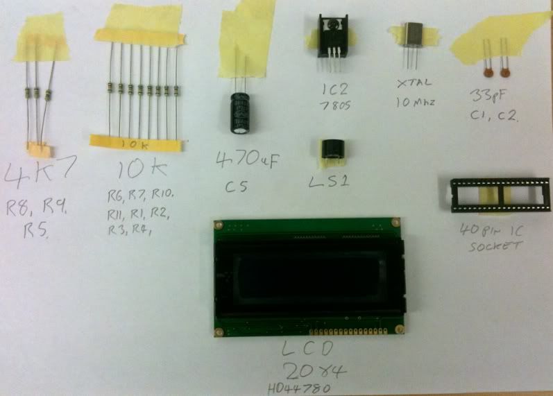
I found a nice heat sink for IC2 off of an old board (I have a box of old boards  ::) ) and LC1 I found on another board
The pic and 10k preset are in the post and I still have to order the keyboard,diodes,100nF caps and SIL socket.

I am unsure about the two 33pf caps as they are just marked 33  :scratch:

Anyway some pics of the board
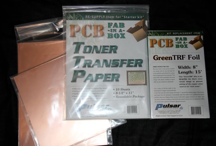
I used toner transfer paper and a laser printer


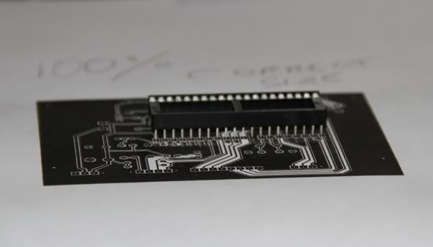
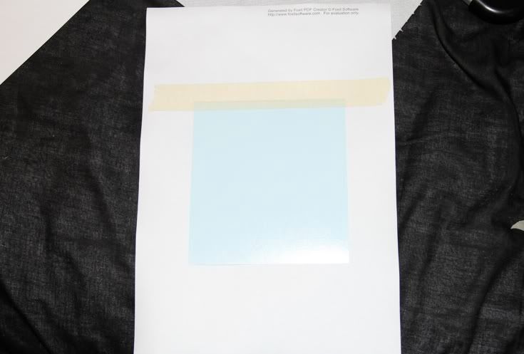
I printed out a test image to make sure it was the correct size


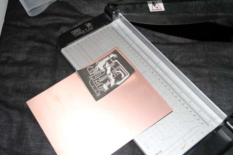
Then used the print to cut out a piece of copper clad pcb
The pcb that comes with the kit is 0.8mm thick which means it cuts great in a paper guillotine


Next I print out another copy and tape a piece of toner transfer paper over the image


And run it back through the printer again


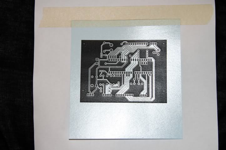
Then I take the toner transfer paper and tape it face down on to my piece of pcb
and run it through this laminator (this is apparently the only laminator that will do this I got mine from ebay)


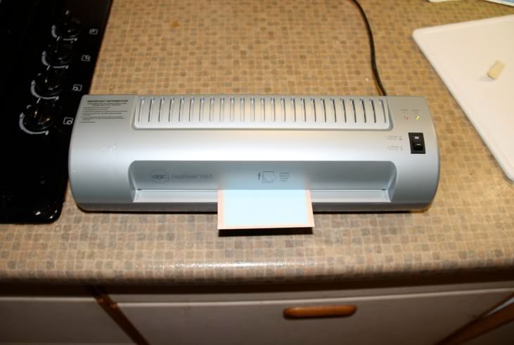
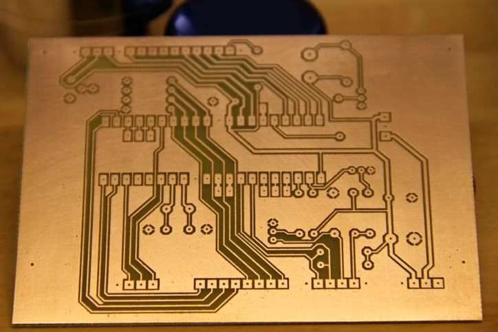
After it has been through a few times I let it cool and then soak it in  water which removes the paper leaving
a black toner mask on the board


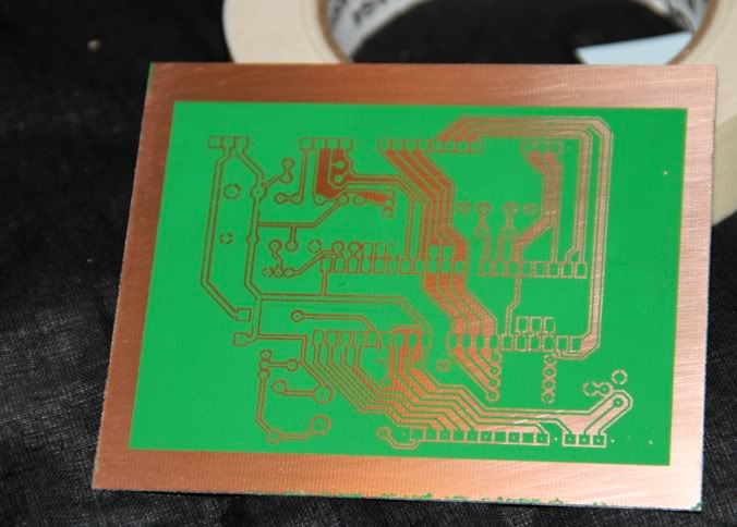
Next I wrap the board in a piece of the green foil which came with the kit and bung it back through the laminator
This is to seal the possibly porous black toner
As you can see it blocks up some of the holes but these lift out with gentle use of masking tape


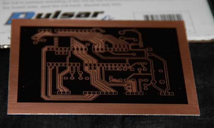
Almost there now but no pics of the etching process
I placed the board in a plastic tub with warm ferric chloride and gently brushed the board with a paint brush ( as I'm impatient )
Rinsed the board and cut off the edges with the guillotine then finaly removed the toner mask with some scotch brite


Just need to drill lots of tiny holes now :dremel:

Jason

Offline Brass_Machine

  • Administrator
  • Hero Member
  • *****
  • Posts: 5504
  • Country: us
Re: Another 4" CNC rotary table
« Reply #13 on: October 16, 2010, 06:03:31 PM »
Nice job etching the board. Never thought to use a lamination machine to press the toner. Not a bad idea. Would keep SWMBO happy... me not using her iron and all.

Eric
Science is fun.

We're all mad here. I'm mad. You're mad.

Offline j45on

  • Sr. Member
  • ****
  • Posts: 380
  • My tiny workshop Location Ashford Kent
Re: Another 4" CNC rotary table
« Reply #14 on: October 16, 2010, 06:12:24 PM »
Eric
According to the company that sell the toner kit they claim that only GBC laminators work because they have heated rollers
Apparently other laminators heat between the rollers and don't work
Jason

Rob.Wilson

  • Guest
Re: Another 4" CNC rotary table
« Reply #15 on: October 16, 2010, 06:14:01 PM »
Hi Jason  :clap: :clap: :clap: :clap:   

i am watching with interest  ,,, GREAT STUFF  :D


Rob 


tumutbound

  • Guest
Re: Another 4" CNC rotary table
« Reply #16 on: October 16, 2010, 06:20:51 PM »
Eric
According to the company that sell the toner kit they claim that only GBC laminators work because they have heated rollers
Apparently other laminators heat between the rollers and don't work

There's an article here  about improving the GBC laminator for this sort of work.

[While you're there, check out their article on building a spot welder  :thumbup:]

Offline Brass_Machine

  • Administrator
  • Hero Member
  • *****
  • Posts: 5504
  • Country: us
Re: Another 4" CNC rotary table
« Reply #17 on: October 16, 2010, 07:16:15 PM »
Eric
According to the company that sell the toner kit they claim that only GBC laminators work because they have heated rollers
Apparently other laminators heat between the rollers and don't work

There's an article here  about improving the GBC laminator for this sort of work.

[While you're there, check out their article on building a spot welder  :thumbup:]

Great info and link!

Thanks

Eric
Science is fun.

We're all mad here. I'm mad. You're mad.

Offline kwackers

  • Sr. Member
  • ****
  • Posts: 356
Re: Another 4" CNC rotary table
« Reply #18 on: October 17, 2010, 04:46:48 AM »
Nice PCB! Good luck drilling the holes - I always miss one. Many's the time I'm trying to squeeze a carbide drill between components on a nearly completed board...

BTW the 33 caps are in pf so you are correct. Looks like you'll be able to test it soon! You can test it without plugging it into stepper drivers etc. Even without a keypad you can still see the startup splash screen (check the contrast if not! ;-)
You can also mimic the keypad with a bit of wire if you don't have one - just look at the 8 pins R1-R4 and C1-C4, by 'shorting' a row pin to a column pin you can 'press' a key.

It's also a good idea before the IC is plugged in and the LCD connected that you apply power and check the voltage to the IC power lines is 5v (otherwise you'll sulk - particularly if you lose the LCD...)

To mount the LCD (so that it could be removed should I ever need to) you may wish to use SIL headers and sockets (the sockets I made simply by cutting up old IC sockets).
Even if you don't use the headers the best way is to bolt the LCD to the pcb using the standoffs and then feed the wires through both and solder them up. For a while you can bend the LCD up out of the way on it's wires if you need to, obviously too much and the wires will snap.
If you use the SIL headers and sockets, solder the sockets to the LCD and bolt the LCD to the PCB then push the headers through from the back until they're a good fit into the socket (this is the easiest way to get them the right length) then solder them up.

Offline raynerd

  • Madmodder Committee
  • Hero Member
  • *****
  • Posts: 2893
  • Country: gb
    • Raynerds Projects - Raynerd.co.uk
Re: Another 4" CNC rotary table
« Reply #19 on: October 17, 2010, 05:12:04 AM »
...without a keypad you can still see the startup splash screen (check the contrast if not! ;-)

Yes, that has caused me hours of pointless trouble shooting!


Nice going - your PCB looks excellent!

Offline madjackghengis

  • Hero Member
  • *****
  • Posts: 717
  • big engine
Re: Another 4" CNC rotary table
« Reply #20 on: October 17, 2010, 08:48:10 AM »
j4son, hi, I am glad you decided to do your build log on the electronics, I am about to embark on a parallel build for my own rotary table, and have just joined the CNC website Kwackers posted his build on, to get the information, thanks Kwackers, for putting this out in public, I never would have seen it without Chris' build, and would never attempt it without your having tried it first, and "cut a path", you don't know how much your work is appreciated.  I have to say a couple things:  first, pc board making has changed much since the last time I did it, I had to burn onto a clear sheet, spray on etch resist coat on the blank board, and put the board and circuit on clear in a glass topped box out in the sun for a few minutes, before sticking it in ferric chloride and etching.  Having made hundreds of boards at a time this way, in a factory for the initial run, use carbide drills only, and when they feel dull, they are, don't use them any more, at risk of having to do some mining, and digging.  I haven't decided how to do my board yet, I don't have all the equipment you do, but you have shown the board is a workable issue, even if it has been since 81 since I last made a board.  That's a great start, I'm glad you're using so many used parts, as I may be able to copy, and what was said about huge capacitors is dead on right, it works.  I'm wondering if I threw away a useable keypad when I disassembled the last microwave oven I threw away.  Make lots of pictures so us slow folks can keep up please.   :poke: mad jack

Offline Spurry

  • Sr. Member
  • ****
  • Posts: 346
  • Country: england
  • Norfolk, UK
Re: Another 4" CNC rotary table
« Reply #21 on: October 17, 2010, 08:57:23 AM »
This looks like an EGHSHO project! Every Good Home Should Have One. Does anyone one know if a DXF drawing of the hole positions is available from anywhere? It would be very tedious to drill all those tiny holes manually.

Thanks  :wave:

Pete

Offline j45on

  • Sr. Member
  • ****
  • Posts: 380
  • My tiny workshop Location Ashford Kent
Re: Another 4" CNC rotary table
« Reply #22 on: October 17, 2010, 09:28:19 AM »
Time to drill some holes  :dremel:

First off I got board trying to drill the holes with a pinvise and a 0.8mm drill (smallest I have)
so I got out the dremel workstation and proceeded to FUBAR the board  :scratch:
Tying to line up the tiny holes in the copper is no fun especially when you pull the handle and the drill decides to go another way

sorry for the poor pics
So I etched another board and had a look at the drill press
I raised it up on some scrap wood


And hot glued a old webcam under the table  :loco: stick with me


view from webcam


I taped a bit of scrap pcb down and drilled a hole


Then I stuck a piece of OHP film to my monitor (cling film would probably work to)
and marked the hole with a sharpie  


Then drilled a few more test holes and was happy enough to have a go at the new board
it's not perfect but should do if I was to do this again I would be less impatient and purchase some smaller drill bits


I think with a better aligned and focused web cam and a better press or use my mill  :doh:
That this would be a very accurate way to drill pcb holes

Please bear in mind that I used 0.8mm thick pcb I don't know how well light would shine through thicker pcb
« Last Edit: October 17, 2010, 09:33:41 AM by j45on »
Jason

Offline kwackers

  • Sr. Member
  • ****
  • Posts: 356
Re: Another 4" CNC rotary table
« Reply #23 on: October 17, 2010, 10:53:27 AM »
Have you missed one? Certainly looks like it..

Far right hand one on the keyboard connector.

Drilling holes in PCB's is something you develop a knack for. I have small drill just for that purpose. The work area needs to be well lit and I tend to quickly bring the drill down to the PCB to check position then a quick jab and it's through and on to the next one. Once you get used to the amount of 'parallax' error etc then it takes about half a second a hole.

I like the webcam idea though!
« Last Edit: October 17, 2010, 10:56:04 AM by kwackers »

Offline j45on

  • Sr. Member
  • ****
  • Posts: 380
  • My tiny workshop Location Ashford Kent
Re: Another 4" CNC rotary table
« Reply #24 on: October 17, 2010, 11:06:15 AM »
Looks like I will be etching another  :(


My grip slipped while I was shearing the board to size  :bang: Third time lucky I suppose.

Kwackers
Looks like I did  :doh: I have loads of PN222A transistors would they be any good for this ?
Jason