.... With a little difference.
Difference being it's for the back of a car

Another request from a car club member.... "can you make me a bracket to hold this (6"TV) about here?"
Well, yes was the answer... What do you want it made from and to look like? "I don't know.... That's why I asked you!"
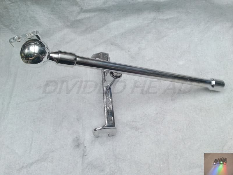
So, here is what I came up with.
I sat in my 'shop and wondered about the hows and whats I could use and make to hold it where it was needed, then while searching through my metals draw I picked up an old twisted 3/8 drive 12" extension..... Oooo I thought.... This could work? He's a mechanic like me so I thought of gearing it towards that.... Extension bars looked like they would do the job. I ordered a set from e-blag for 4 notes and then just had to make something out of them. Then just make a tilting mechanism for the head.
A crap-o-cad or two later and I started making parts


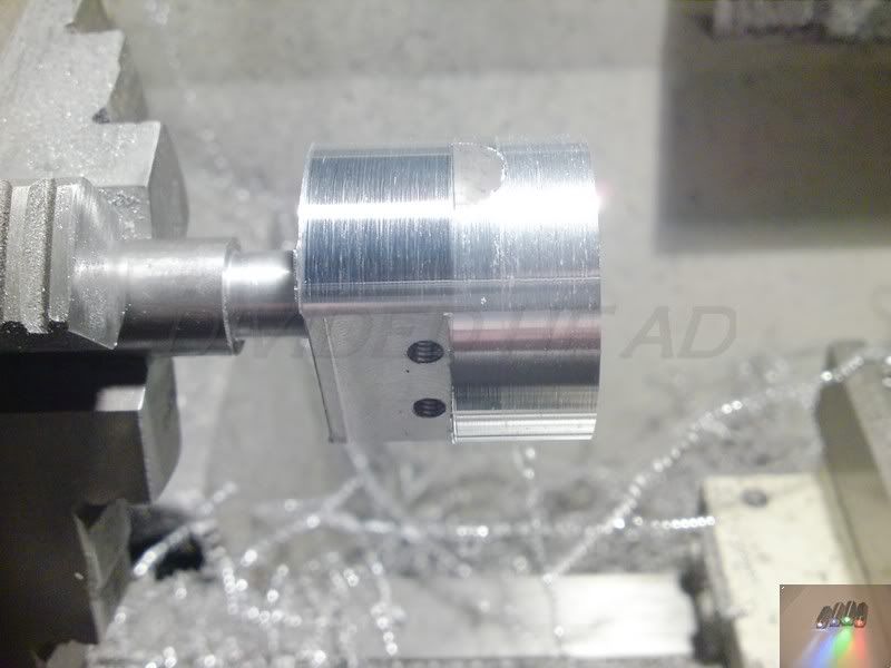
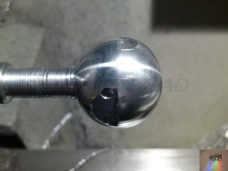
I Ball cut into the fixed side of the pivot and drilled and tapped it for the top extension that has been milled to half thickness. I could have used a regular endmill or slot drill but i decided that this way would allow me to keep register with the centre of the cut for the drilling and threading part.
The end was shaped on the grinder to save a little set up time with the lathe. If it was on display I'd have used the radius turner.
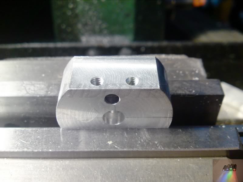
The moving side of the pivot is then drilled through and recessed for the pivot bolt, drilled just above that for the spring and ball bearing then milled flat on top, drilled and tapped m4 (try to ignore the off centre appearance, the whole part is 8mm over sized and will be turned true when bolted together)
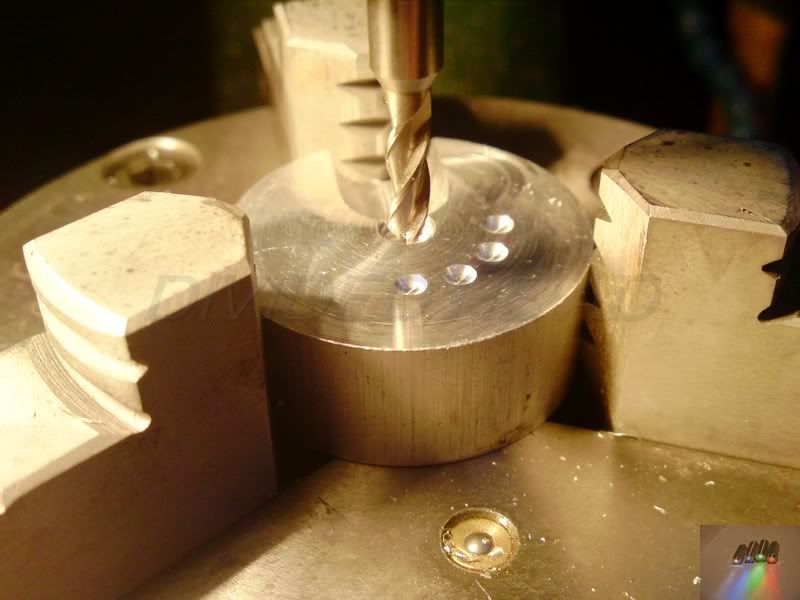
The fixed side has the recesses made for the ball bearing to seat in when the head of the bracket is tilted.
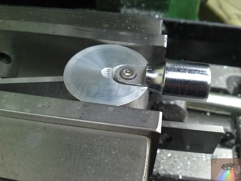
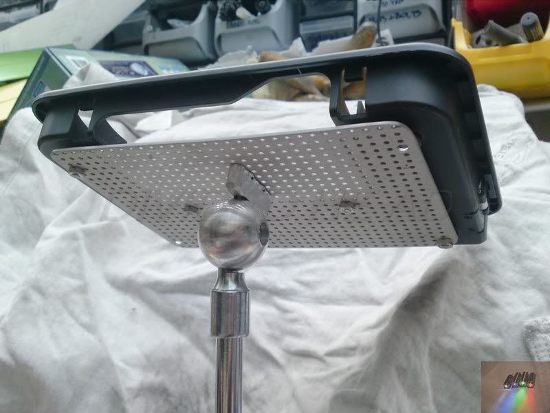
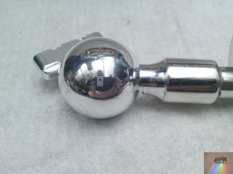
An arbour is made to clamp the 2 parts together and it is turned spherical (cause I can)
A plate is made to fit the rear of the TV mounting and a connecting piece made to join it to the pivoting head.
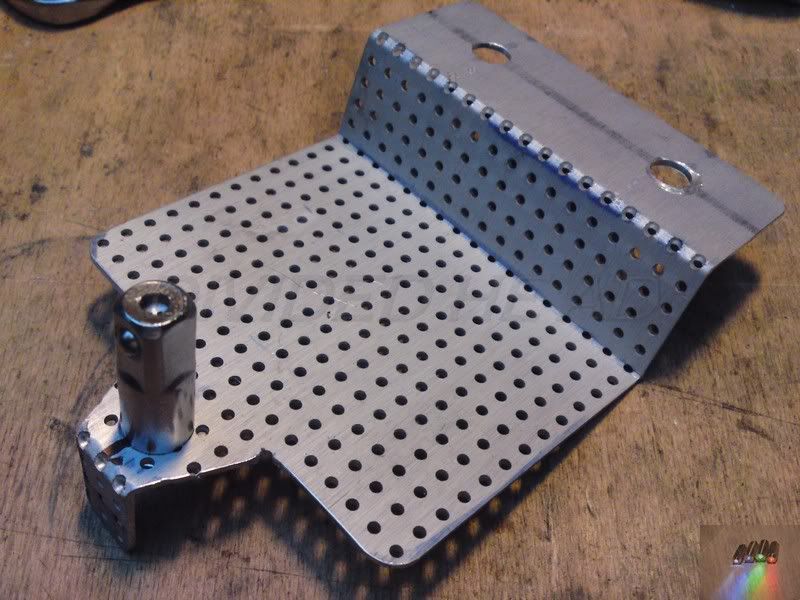
A base plate is made up from the same ali plate used in the mounting above and the lower extension part bolted to it.
Now, stability being a major issue I decided it needed a way of well, erm, stabilising it.... "cross bracing with a spanner methinks!" This was the not so easy to make solution (mkIII)
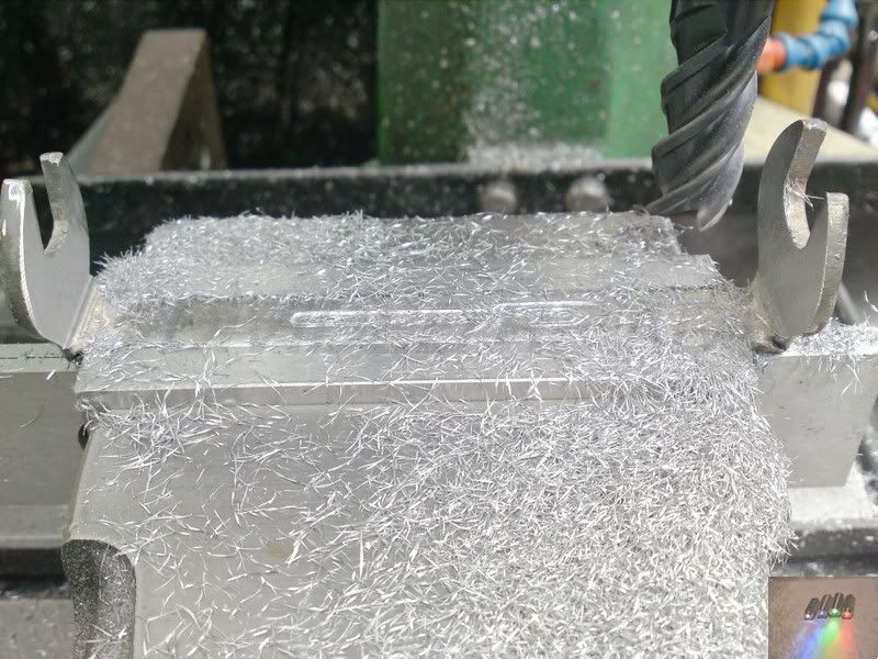
I used a ball endmill to cut across the spanner neck. To thin and create a weaker point for the heat and a relief for the bend.
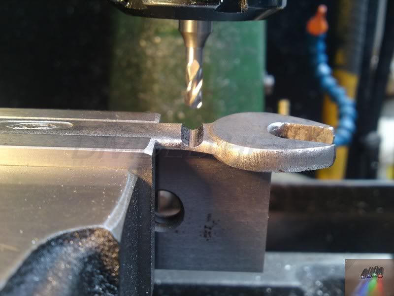
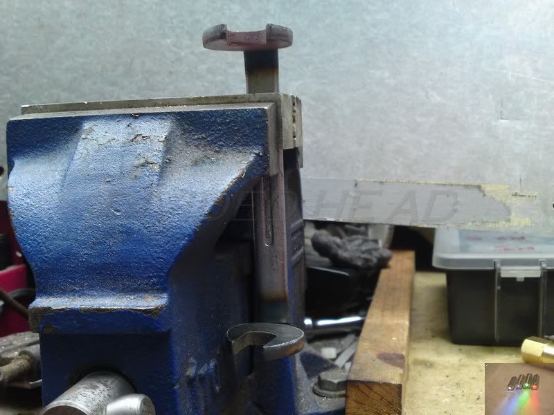
Note the big steel heat deflector behind the vice, stuff melts pretty easy in the presence of a big blue flame!
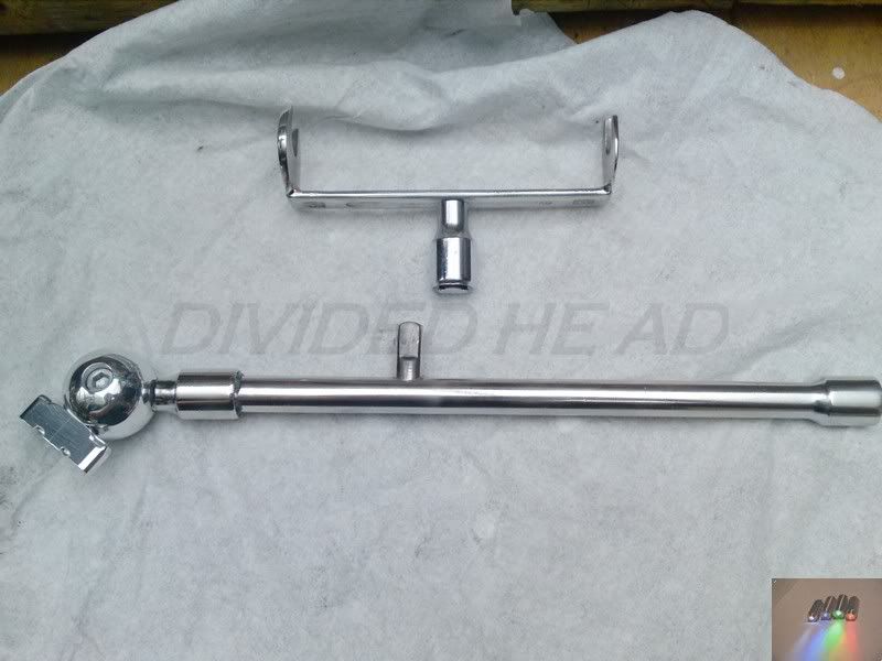
The bend joints were then silver soldered to add strength to the bend and then the heads were machined with a carbide endmill to get the required width between them. 112mm.
I have no pics of the failures, but you're welcome to see them it you like? just know that this was the only way to get a spanner to bend pretty accurately with propane and a vice!
The spanner was drilled and recessed through the centre to mount a female extension end to it using a m4 dome head screw. (no pic's of that one?)
The upright needed the male counterpart for the cross bracing so using a slot drill cut a countersink into the upright and silver soldered the male part to it... (sounds bad that!

)
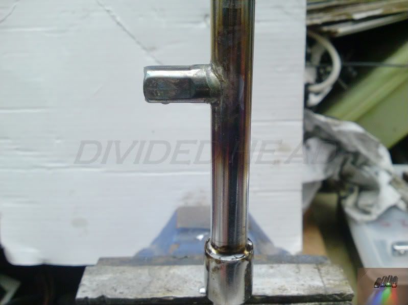
I also soldered the top part to the end as it was far too wobbly to control, as long as the lower joint could be separated that was fine.
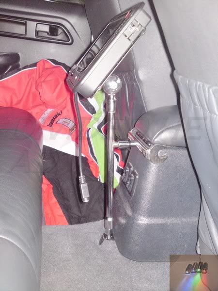
Finally I polished it all up and sprayed the ali plates black.
Then finally fitted to the car.... Sorry for the wonky shots, it's hard to get photo's in a tight space.
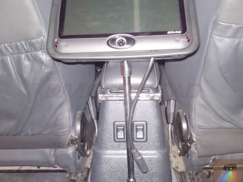
Another happy ( I would say customer but that'd be a lie. At least he paid for the parts!) friend
I know, loads of photo's.... But I gotta get the info across
Well that's the last few weeks done, on holiday soon

(vacation for some of you guys) so will be a little quiet. But that's not till Wednesday

I'd forgotten how time consuming this posting business is

Ralph.


