Occasionally in order to justify the amount of crap I have lying around I'm forced to demonstrate it's usefulness...
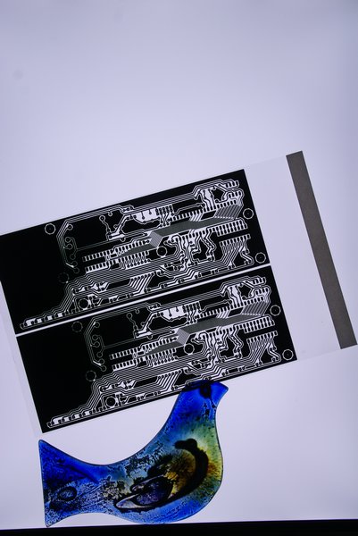
My other half does a lot of 'hot glass' work and wanted a light box and since we throw LCD monitors away almost weekly at work I figured it should be an easy thing to do.
So this was my 4th LCD conversion attempt. The first had a duff inverter so was useless (or at least couldn't be used for free). The 2nd worked when I plugged it in (can't bring myself to cannibalise working stuff). The 3rd turned out to have a minor fault when I was figuring out how it worked so it got fixed and...
Finally the 4th one turned out to be suitable (although I didn't look too hard at why it didn't work). Model was a NEC LCD 1970NX.
I stripped it down to basics, removing all the control electronics and LCD panel, leaving just the PSU and 'light box'.
On stripping it down the first thing I noticed was the inverters for the cold cathode tubes and the power supply were on the same board - this could make life easy...
Next they'd thoughtfully labelled the socket coming off it - 12v, 5v, Gnd, PWM, On. Wasn't getting any harder...
As a background most LCD monitors have a separate inverter circuit for the lights (even this one with a quick inspection showed it would be possible to hacksaw the power supply board in two to separate out the inverters if it proved the PSU was broken). The inverter section usually runs off 12v, has some way of turning it on and off and a PWM input to control the brightness.
With this in mind I applied power and first checked if the supply was working (it was), then I checked the voltage on the 'on' input - that was 0v which suggests it needs pulling high (probably 5v) to switch on the inverters. Next I breadboarded a 555 as a PWM generator, hooked the output to the PWM input and pulled the 'on' input high - and....
It worked! Not only that but adjusting the PWM ratio altered the brightness from off to full (blinding) brightness. Only issue was my PWM was running at around 100hz and this was causing flickering on the panel, changed the value of the pot to get this up to around 1khz and this got rid of the flickering.
Since the surface is only plastic I got some 2mm picture frame glass, this is almost exactly the same thickness as the LCD. This allowed me to refit the bezel and re-use the original monitor case (the back is flat so it will lie down - or can be 'hooked' onto the original stand for vertical use).
I now simply re-made the PWM on a bit of strip board and refitted it all into the original case.
Total time probably about 4 hours.
The only change I'd make is to use a small 8 pin PIC as a PWM generator, unfortunately I'd run out so couldn't (got some on order though). With a PIC you could re-use the front panel controls, get the on-off button to toggle the 'on' line to switch it on and off, and use the brightness up down buttons to ramp the brightness. The front panel on this monitor is slightly damaged (missing buttons) so I need to see if it can be rescued if so then I'll probably do that next, whilst the current brightness and mains on/off switch is OK being under the monitor makes it hard to get at whilst it's lying flat on it's back.
If you want to try this - remember there are some high voltages floating around the PSU - upwards of 800v even when unplugged!
Anyway some pics:-
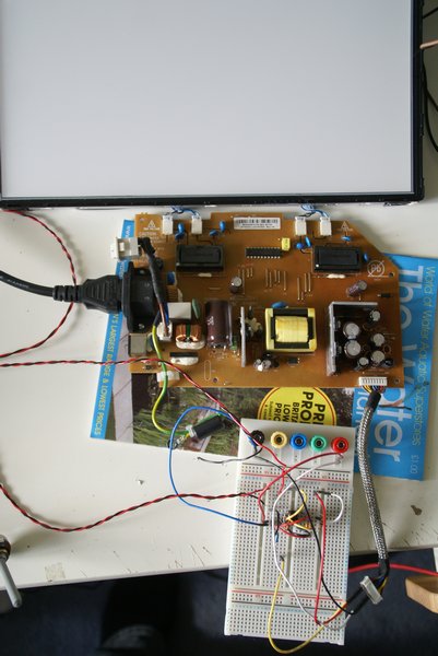
Stripped and with the PWM breadboarded.
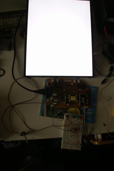
Working!
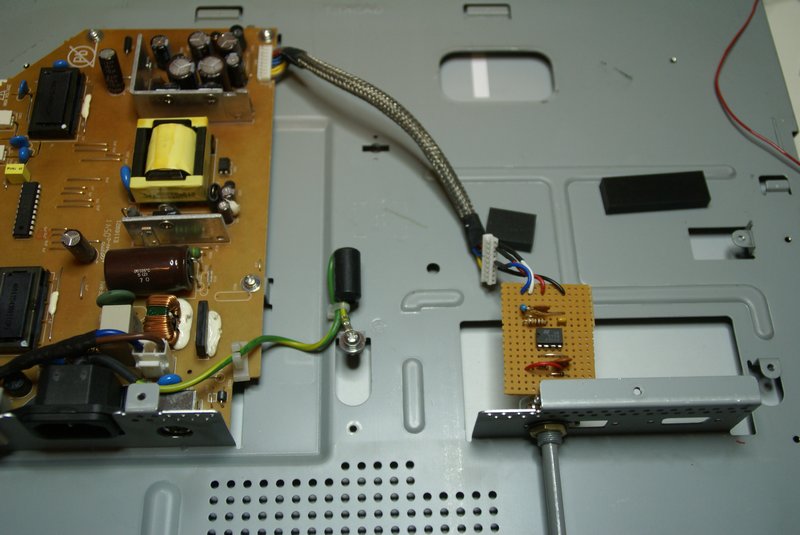
Putting it all together.
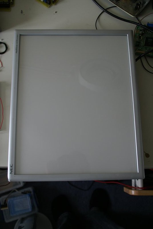
Finished.