To ieezitin, I have been welding up custom frames for about twenty years, ever since I bought a decent mig welder, and had the shop to do it in. I was not happy with the quality nor the choices offered in "custom" frames, and I've welded up too many repairs in stock frames, so there had to be a third choice when I finished raising my children, and got back to building bikes, engines, and the like. I've gone through many changes, two previous designs of tubing benders, different tube and many methods of making things fit. Grinding will get you close enough, but machining gets you right on. Grinding takes just as long, and the test fits always piss you off. Becky, my biker buddy, knows she's getting a great frame because she wanted mine, and I told her I'd build her a duplicate, but mine's not for sale.
For twenty years, I worked when I could where I could doing what ever I could get for outside work, while I served in the Marine Corps. I was medically retired due to the onset of Multiple Sclerosis in 97, but had served some four years with it before it got bad enough I couldn't lead from the front, so I had plenty of time to get ready to be retired out. My wife and I bought our "farm", about sixty acres out in the country, the shop is about fifty feet from the house, and I walk to work every day. I barely make enough to cover the electric and other "costs" of running the shop, but I can't sit, there's things I want but can't buy, and there's jobs to be done no one else wants to do, mainly repairs to old and antique machinery, being used still, because that's what's around, and I like fixing things. The best part about this forum is that I get to watch what other people love to do, and thus do a great job at it, and see and learn, and I get to share my own trials and tribulations, taking the hints and ideas I get, and improving my tool kit as I go. As I see it, if you can't learn something every day, you're not trying. Being better than yourself tomorrow than you are today is the best way to build a good perspective of yourself, and gives you a challenge you can fulfill each and every day pretty much, and people who know they know how to do things are generally happy people. I've done pretty much the same thing my whole life because there's never an end to broken old things that people want back because the new replacements aren't as good. The pay's not great, but the people are, I make a living, and I'm happy, they're happy, the taxman is happy, and I sometimes even get to town more than once in a month.
In working on the oil pump body for the engine, I ran into a small snag. The sump pump, which extracts the used oil and returns it to the tank via a filter, went fine, with little problem as the inlet is a groove "routed" with an 1/8 in end mill on the working face of the pump body, which goes against the rear main bearing, and the outlet goes out through the side of the pump body, through a matching hole in the crank case, and returns to the oil tank. The pressure oil pump, which takes oil from the tank and feeds it in to the rear main bearing, through passages in the crankshaft, oiling the master rod directly, and the slave rods with spray flung by the crank, then on to the front main bearing, after which it seeps out into the front gear cavity where the gear train driving the cam are housed.
To get the pressure fed oil to the crank, I drilled an 1/8th inch hole through from the outside of the pump housing, aligned across the middle of the pump its self, and through the body in, where it will guide the drill to open a hole in the side of the rear main bearing, and thus apply the pressure to that bearing, and thus all the way through the oil system as described. The problem is the hole to feed the pressure pump should be going under the pump cavity, with a hole drilled to connect it to the inlet side of the cavity, a hole connecting it to the output side, and with the quarter inch or so of space under the cavity, blocked off after drilling the hole in the bearing, to separate the gravity feed to the pump, from the pressure output which should be going to the bearing. In following the design drawings, I found that I ended up drilling the 1/8th inch hole with perhaps .025 of the hole penetrating the gear cavity, allowing pressure oil to flow back to the inlet side without ever leaving the pump, via the slot in the gear cavity. I should have done the math, simply subtracting the depth of the gear cavity (.188) from the total thickness of the pump body (.468), and calculating the stated entry point on the side of the body, which would have led me to see the drill would end up through the gear cavity. The eighth inch oil port is counter bored for a quarter 28 thread for the oil fitting and I could have kept the counter bore on center of the body, and drilled the 1/8 in port off center in the counterbore, allowing it to pass under the gear cavity, and putting a plug directly under the gear cavity, held in with loctite, to separate the inlet from the pressure feed outlet, but this is all consideration after the fact. I have two choices, and the first does not eliminate the second. First, since the pump body is line reamed with the rear main bearing, I can attempt to fix it by putting a piece of 1/8th inch aluminum rod in the drilled hole where it penetrates the gear cavity, weld a quarter inch piece in place, blocking inlet from outlet, and milling the weld down to the bottom of the gear cavity. If I can do that without distorting the pump body, it will be the best answer, I think. The other choice is to turn a new blank pump body, set it up as the first one was with the rear main bearing, and do my best to align ream the shaft holes in the new pump body without distorting the reamed holes in the rear main bearing, and from there, taking lessons learned, and getting the pump feed passage beneath the gear cavity and thus only needing plugging. The key issue is not distorting the reamed holes in the rear bearing, as that chunk of bearing bronze was about fifty bucks, and I don't want to buy another chunk, and make a new rear main bearing.
using an 1/8th in ball mill to mill the inlet passage for the pressure pump feed
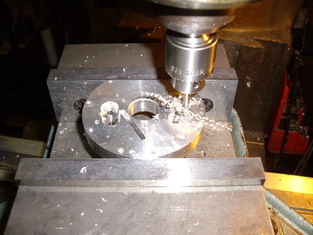
using the same cutter to mill the pressure pump output port to provide pressure to the rear main bearing, note the long groove machined on the left side angled slightly from the center at its base, to the scavenge pump cavity at the top of the groove, this is milled with an 1/8th in ball mill, to intersect with the passage from the oil sump
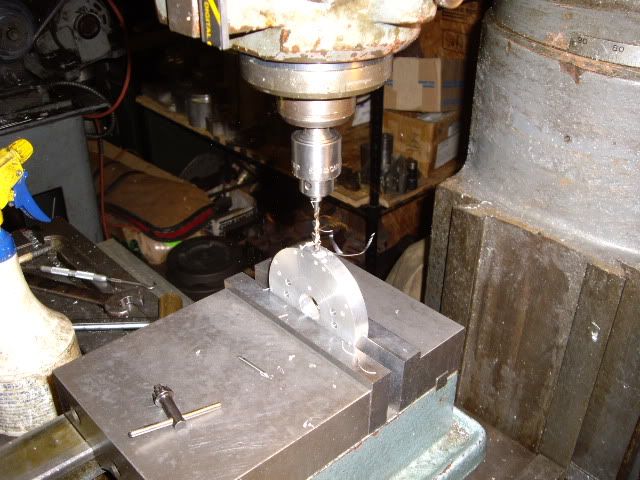
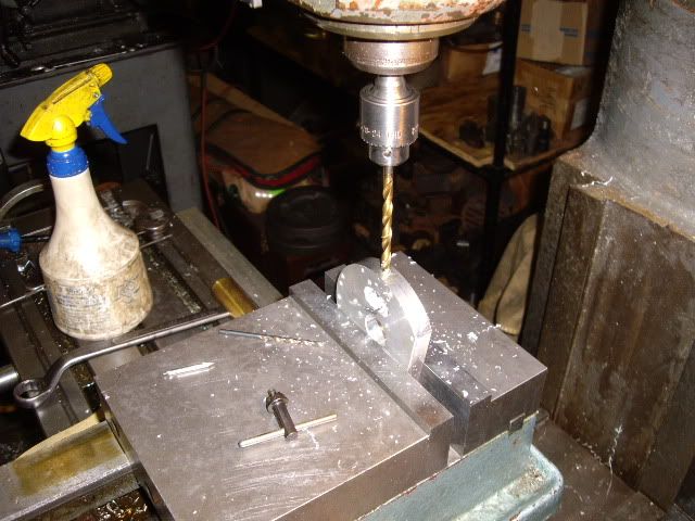
drilling the 1/8 inch port feeding the scavenge pump, this port will intersect the groove milled in the face of the pump body leading to the scavenge pump.
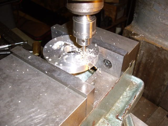
counterboring the oil feed for 1/4-28 infeed oil fitting, this is counter bored at 5/16ths .032 deep for a sealing o-ring between pump body and crank case, the 1/8th inch hole has been drilled through to the center hole which slips over the rear main bearing, and this hole will guide drilling the oil hole in the main bearing allowing pressure to flow through the crankshaft feeding all the bearings and gears
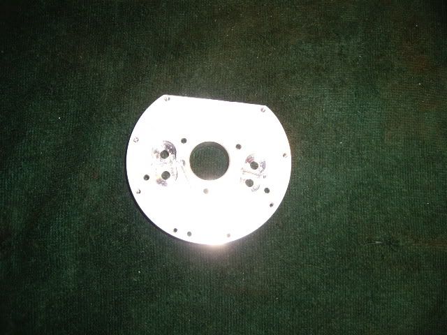
the working face of the pump body, with the gear cavities showing. Note the groove in the middle of the gear cavity on the right, this is where the feed drilling broke into the gear cavity and needs resolution.
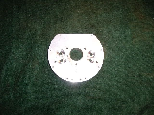
another picture of the pump working face with the pump cavities showing.
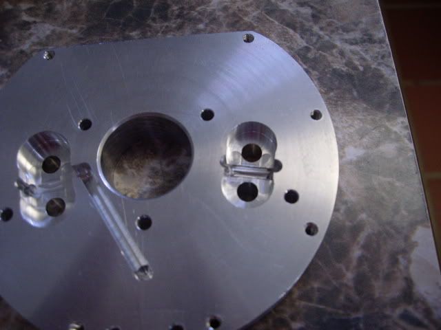
a close up showing the pump gear cavities with the scavenge on the left, with the angled slot feeding it, the pressure pump gear cavity on the right, note the groove across the middle of the gear cavity, this cannot remain and the pump move oil.
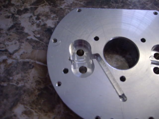
picture of the scavenge pump up close, with the feed groove visible, and the hole for the outfeed visible on the left edge of the cavity centered on the side, this intersects with a drilled passage from the left edge of the pump body which is also counterbored for an o-ring, to seal against the crankcase when the pump and main bearing are in place.
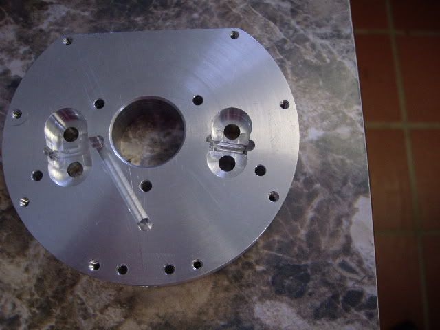
showing the whole of the unfinished pump body, with the feed groove of the scavenger pump seen leading to the pump cavity, and the bottom end of the groove having a hole connecting it to the drilled passage that comes up from the bottom edge of the pump body. This picture shows the unwanted groove in the feed pump clearly, on the right side. When the pump body is finished, most of the metal will be gone, with it being approximately "T" shaped, scavenging up through the vertical of the "T", pumping used oil out, through the left arm of the "T", to a filter to the external tank, and taking in fresh oil through the right hand arm of the "T", and pressure feeding it through the rear main bearing, through the crankshaft, to all the bearings and the gears to fall to the sump and be cycled through again. I expect the fix of welding up a plug for the groove to work otherwise I will be machining a new body out of new material, with a different "take" on the feed intake oil passage, one not requiring welding up the body hopefully. This may appear a setback, but no project moves to completion without glitches, and this is really a rather minor one and just a slight pain, not a worry. I'm looking to see the end of this little aspect hopefully today. Ta Ta for now,


mad jack


